
User manual


APPENDIX
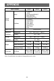
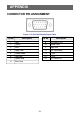
CONNECTOR PIN ASSIGNMENT
1
5
6
10
11
15
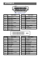
Figure 6 15-Pin Color Display Signal Cable
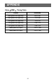
Pin No.
Description
Pin No.
Description
1
Red
9
+5V/Sense(+5V)
2
Green
10
Monitor Gnd
3
Blue
11
Logic Gnd
4
Logic Gnd
12
DDC serial data
5
Detect cable
13
H sync
6
Red Gnd
14
V sync
7
Green Gnd
15
DDC serial Clk.
8 Blue Gnd
23