CONTINUING TO MANUFACTURE AND SELL QUALITY SCHABEN PRODUCTS. operation & maintenance manual 8500 BAKERSFIELD, CA 4450 STATE RD, 93308 877.724.2236 COLUMBUS, NE 5834 E 23RD ST, 68601 800.274.1025 V I S I T DOTHAN, AL 1563 S OATES ST, 36301 800.227.4098 U S GREENWOOD, MS 104 EASTMAN ST, 38930 800.844.4524 O N L I N E @ SERIES SPRAYER HOPKINSVILLE, KY 1100 NEW INDUSTRY LN, 42240 800.637.7172 NEWTON, KS 7000 SCHABEN CT, 67114 800.394.7662 OTHELLO, WA 81 E PINE ST, 99344 800.634.
INTRODUCTION 1. Read and understand the Operators Manual and all safety signs before using. 10. Do not breathe, touch or ingest chemicals. Always wear protective clothing and follow safe handling procedures. 2. Place all controls in neutral, stop tractor engine, turn monitor off, set park brake, remove ignition key, wait for nozzles to stop spraying before servicing, adjusting, or repairing. 3. Before spraying a field, be familiar with all potential hazards: trees, rocks, ditches, gullies, etc.
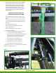
FIG. 1 14. Consult tractor manufacturers manual for hydraulic operation system.(open or closed center system) For closed center systems, leave hydraulic boom operation block located on the center of boom as factory installed (see figure 4). For open center hydraulic systems, the by-pass (dump) valve needs to be put back in th place of the by-pass (dump) plug (see figure 3).
FIG. 3 T O P O F S P R AY E R B O T T O M O F S P R AY E R OPEN CENTER SYSTEM FIG.
SPRAYER OPERATION FIG. 6 DO NOT PULL AT ROAD SPEEDS WITH PRODUCT IN MAIN TANK Electrocution hazard. Keep away from power lines. To prevent serious injury or death from electrocution: 1. Stay well away from power lines when folding or extending wings. Electrocution can occur without direct contact. 2. Lower wings completely before moving or transporting. BOOM OPERATION FIG. 7 * Mount 7-function control box in a convenient place for easy operator access.
FIG.5 left outer boom pivot function. Move the switch up and hold to pivot the left outer boom in and down to pivot out. Release the switch, the left outer boom will stop and remain at that position. 6. RIGHT OUTER BOOM SWING: This spring-loaded-to-neutral-center toggle switch controls the right outer boom function. Move the switch up and hold to pivot the right outer boom in and down to extend. Release the switch, the right outer boom will stop moving and it will remain at that position. 3.
FIG. 14 locked down hold the toggle switch down for 5 seconds after the boom is fully extended. (see figure 15) 5. Hold down on “main lift” boom switch to lower boom to desired spray height. To ensure optimal boom performance never run boom in fully down position. Doing so eliminates boom ride accumulator. 6. Reverse the above procedure when converting from field to transport configuration. IMPORTANT: Once tower cylinder bottoms out raise 1”. 1.
FIG. 16 PLUMBING OPERATION 1. Connect supply hose to quick fill valve (valve 3) (If top filling, open lid and insert supply hose.) “WARNING!” Be careful if crawling on sprayer. Steel surfaces can become slick when wet. Also watch head while climbing onto sprayer if in transport position. Operator must go under boom to access platform. 2. Make sure main tank valve (valve 1) is open. NOTE: Make sure rinse tank valve (valve 10) is closed before filling.
reaches 3/4 of desired capacity. solution. NOTE: Follow all chemical manufacture label instructions. 8. 9. When solution reaches desired tank level, close quick fill valve (valve 3) and/or stop solution from being added to sprayer. Disconnect supply hoses, secure all sprayer covers. Continue to run sprayer pump to circulate sprayer 10. Fill auxiliary tanks as needed. - Rinse - Safety wash - Foam Marker 11. Allow solution to circulate for several minutes before applying.
OPTIONAL SPRAY CONTROLLER SPEED SENSOR LADDER & TOOL BOX FIG. 19 LADDER Raise the ladder into the vertical position and push over and down to secure in the locked position. The lock is part of the ladder anchor bracket. Position the ladder in the up and locked position whenever the sprayer will be moved. (see figure 19) FIG. 17 TOOL BOX FIG. 18 The platform of the machine is designed to provide storage for the operator. Lift the floor of the platform to access the storage compartment.
INITIAL START-UP 1. Follow label instructions for proper mixing of foam concentrate. Fill tank with desired amount of water and then add foam according to label. It is better to have more foam concentrate added to the water than less, because liquid flow amount can be regulated by Wet/Dry knob. NOTE: Start with control knob at center position. travel from the control valve (144f-1-3) toward the right or left side of the boom. Reverse the L/R toggle switch and foam will travel the opposite direction.
FIG. 11 BREAK-IN Although there are no operational restrictions on the sprayer when used for the first time, it is recommended that the following mechanical items be checked: A. After operating for 1/2 hour 1. Re-torque all the wheel bolts. 2. Re-torque all other fasteners and hardware. 3. Check that all electrical connections are tight. 4. Check that no chemical or hydraulic lines are being pinched or crimped. Re-align as required. 5. 6. B. Check that all nozzles are working properly.
3. Follow good shop practices: - Keep service area clean and dry Be sure electrical outlets and tools are properly grounded 4. 5. 6. Use adequate light for the job at hand. Before applying pressure to a hydraulic system, make sure all components are tight and that steel lines, hoses and coupling are in good condition. Before applying pressure to chemical system, make sure that all connection are tight and that all hoses and fittings are in good condition.
SPRAY CONTROL VALVE WIRING FIG. 12 - The motorized ball valves equipped on the sprayer require 12V+ constant power and ground to make actuate. When 12V+ is sent from the controller thru the signal wire per each section the valve will open as long 12V+ is present to the section wire. Once power is removed by turning off the individual or master switch, the valves will close. - Each motorized ball red wire connects to the 12V+ terminal.
PLACING IN STORAGE At the end of the spray season, the machine should be thoroughly inspected and prepared for storage. Repair or replace any worn or damaged components to prevent any unnecessary down time at the beginning of the next season. Follow this procedure: 1. Thoroughly wash the machine using a hose or a pressure washer to remove all dirt, mud, debris or residue. 2.
8500 SERIES SPRAYER operation & maintenance manual BAKERSFIELD, CA 4450 STATE RD, 93308 877.724.2236 P: 661.391.9081 • F: 661.391.9085 BAKERSFIELD@AGSPRAY.COM HOPKINSVILLE, KY COLUMBUS, NE 5834 E 23RD ST, 68601 800.274.1025 P: 334.673.0580 • F: 334.673.1974 NEWTON, KS OTHELLO, WA COLUMBUS@AGSPRAY.COM 7000 SCHABEN CT, 67114 P: 270.885.0296 • F: 270.885.7392 P: 316.283.4444 • F: 316.283.4646 HOPKINSVILLE@AGSPRAY.COM 800.227.4098 P: 402.564.4544 • F: 402.564.