™ Dual Fuel User Guide & Installation & Service Instructions U110054 - 03A
Contents 1. Important Safety Information In Case of Fire To Prevent Fire or Smoke Damage Wear Suitable Clothing Use Only Dry Potholders or Oven Gloves Important Safety Notice and Warning Proper Installation Conversion User Servicing Cooktop burners Use the Right Size Pan Ovens Placement of Oven Racks General Safety Instructions 2. Range Overview Cooktop Burners Wok Burner The Multi-function Oven Operating the Oven Sabbath Mode Energy Saving Panel Feature The Clock Accessories Oven Light Storage 3.
1. Important Safety Information Read all instructions before using this appliance. Save these instructions for future reference. Many plastics will burn and most are damaged by heat. Keep plastic items away from parts of the range that may become warm or hot. Do not leave plastic items on the cooktop as they may burn, melt or soften if left too close to a vent or a lighted burner.
To avoid risk of electrical shock, personal injury, or death, make sure your range has been properly grounded and always disconnect it from the main power supply before servicing. primarily to the incomplete combustion of natural gas or liquid petroleum (LP) fuels. Properly adjusted burners will minimize incomplete combustion. Exposure to these substances can also be minimized by properly venting with an open window or using a ventilation fan or hood.
Use the Right Size Pan Placement of Oven Racks This appliance is equipped with burners of different sizes. Use utensils with flat bottoms. Do not use unstable pans and position the handles away from the edge of the cooktop. Make sure the flames are under the pans. It is not safe to let the flames burn up the sides of the pan; the handle may get too hot. Always place oven racks in desired location while oven is cool.
Always keep combustible wall coverings or curtains etc. a safe distance away from your range. DO NOT spray aerosols in the vicinity of the range while it is in use. Do not store or use combustible materials, or flammable liquids in the vicinity of this appliance. Take great care when heating fats and oils, as they will ignite if they get too hot. Use a deep fat thermometer whenever possible to prevent overheating fat beyond the smoking point. Never leave a deep fry pan unattended.
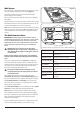
2. Range Overview DocNo.025-0101 - Overview - 90 DF SC - Prof+ FX Fig.2-1 A B OFF OFF C D ArtNo.270-0029 - Prof+ 90SC annotated The dual fuel single cavity range cooker (Fig.2-1) has the following features: 5 hotplate burners including a wok burner B. A control panel incorporating a timer C. A multi-function oven D. A storage drawer HI OFF A. Fig.2-2 LO Cooktop Burners Note: Before using the cooktop make sure all burners are in place and all the grates on the range are properly placed.
Fig.2-3 The igniter should spark and light the gas. Keep holding the knob pressed in to let the gas through to the burner for about ten seconds. ArtNo.272-0002 Prof+ pyro US - Control to low If, when you let go of the control knob, the burner goes out, then the FSD has not been bypassed. Turn the control knob to the OFF position and wait for one minute before you try again, this time making sure to hold in the control knob for slightly longer. HI LO Adjust the flame height to suit by turning the knob.
Wok Burner Fig.2-8 The wok burner is designed to provide even heat over a large area. It is ideal for large pans and stir-frying (Fig.2-8). For heating smaller pans, the aforementioned hotplate burners may be more efficient. ArtNo.311-0047 - Elan 110 Wok burner You can remove the burner parts for cleaning; see ‘Cleaning your cooker’. You should wipe the enamel top surface of the cooker around the hotplate burners as soon as possible after spills occur.
Operating the Oven Fig.2-10 The multi-function oven has two controls: a function selector and a temperature setting knob (Fig.2-10). ArtNo.272-0003 Prof+ pyro US - MF oven controls (2) OFF Function selector Turn the function selector control to a cooking function. Fig.2-11 shows the control set for conventional oven cooking. Turn the oven temperature knob to the temperature you need. The oven heating light will glow until the oven has reached the temperature you selected.
Rack levels 5 and 6 should be used depending on the size of the food being cooked. Fig.2-16 Fan Assisted Oven This function operates the fans, circulating air heated rtNo.030-0028 - Elan MF bysymbols the elements at the top and the base of the oven (Fig.2-17). The combination of fan and conventional cooking (top and base heat) makes this function ideal for cooking large items that need thorough cooking, such as a large meat roast.
Sabbath Mode Fig.2-21 Choose conventional oven or warming oven modes as best suits you cooking needs. Set the desired temperature with temperature selector. The unit will not shut off until the function selector is turned OFF. Energy Saving Panel Feature WARNING! Take great care when removing the divider NOT to scratch the inner glass door surface. Scratches in the glass can cause stress and may cause the door to fail. ArtNo.281-0150 - Oven Divider Fig.2-22 ArtNo.
The Clock Fig.2-24 You can use the 6-button timer (Fig.2-24) to turn the oven on and off. The clock must be set to the time of day before the oven will work. To set the time of day ArtNo.302-0002 - 6BC annotated Press and hold both the [C] and [D] buttons as shown in Fig.2-25. While holding these buttons simultaneously press [–] or [+] until the correct time shows. If you make a mistake or press the wrong button, turn off the power supply for a minute or two and start again.
Fig.2-34 AUTO is showing, you want to reset to manual cooking Fig.2-35 ArtNo.302-0017 - 6BC Deactivating the key lock 1 Pyro When cancelling an automatic setting, any cooking time already set must be returned to ( 0.00) before you can return to manual, by pressing the [B] button. ArtNo.302-0018 Deactivating the key lock 2 pyro Key Lock When the key lock is activated, the clock can be operated as usual but the oven is locked and will not come on. Fig.
Accessories Fig.2-39 Fig.2-40 Oven racks Each range is supplied with the following: ArtNo.326-0013 - Full capacity shelf (Falcon) 2 full width racks (Fig.2-39) 1 telescopic rack with runners (Fig.2-40) 2 broiler pans with grids (Fig.2-41) Fig.2-41 3 energy saving racks (Fig.2-42) 2 sets of side rack supports (Fig.2-43) ArtNo.331-0008 - 90SC grill pan & trivet 1 energy saving divider (Fig.2-44) Fig.2-42 ArtNo.
Oven Light Fig.2-50 Press the button to turn on the oven lights (Fig.2-50). If one of the oven lights fail, turn off the range circuit breaker before you change the bulb. See the ‘Troubleshooting’ section for details on how to change an oven light bulb. ArtNo.320-0017 Main oven light Storage The bottom drawer is for storing oven trays and other cooking utensils. It can get very warm, so do not store anything in it that may melt or catch fire. Never store flammable materials in the drawer.
3. Cooking Tips Cooking with a Multi-function Oven General Oven Tips Remember: not all modes are suitable for all food types. The oven cooking times given are intended for a guide only. The wire racks should always be pushed firmly to the back of the oven. Baking trays with food cooking on them should be placed level with the front edge of the oven’s wire racks. Other containers should be placed centrally.
4. Cooking Table DocNo.031-0004 - Cooking table - electric & fan single cavity 6 5 4 3 2 1 The oven control settings and cooking times given in the table below are intended to be used AS A GUIDE ONLY. Individual tastes may require the temperature to be altered to provide a preferred result. Food is cooked at lower temperature in a fan oven than in a conventional oven. When using recipes, reduce the fan oven temperature by 25°F (10°C) and the cooking time by 5-10 minutes.
5. Troubleshooting Cooktop ignition or cooktop burners faulty If there is an installation problem and I don’t get my original installer to come back to fix it who pays? Is the power on? You do. Service organizations will charge for their service if they are correcting work carried out by your original installer. It is in your interest to track down your original installer.
The timed oven is not coming on when automatic cooking Fig.5-1 Has the oven knob been left in the OFF position by mistake? Is the oven locked (see above)? Oven temperature getting hotter as the range gets older ArtNo.324-0005 Oven light bulb If turning the knob down has not worked or only worked for a short time then you may need a new thermostat. This should be installed by a service technician (see the ‘Service and Parts’ section of the instructions). Fig.
6. Cleaning Your Range Essential Information Fig.6-1 A Before thorough cleaning, turn off the circuit breaker. Allow the range to cool. C After cleaning, remember to switch on the circuit breaker and reset the clock before re-using the range. B Never use paint solvents, caustic cleaners, biological powders, bleach, chlorine based bleach cleaners, coarse abrasives or salt. Do not mix different cleaning products – they may react together with hazardous results. E D Daily Care ArtNo.
Main Top Fig.6-5 Lift away pots or pans from the main top. Remove the grates from the spillage area and carefully place in a sink of warm soapy water. Wipe loose debris from the main top. For best results use a liquid detergent cleaner. Rinse with cold water and thoroughly dry with a clean, soft cloth. Ensure all parts are dry before repositioning. ArtNo.272-0015 - 90DF - Pro+ - Removing the outer door panel Fig.
To remove and refit the telescopic rack and runners Slide the rack out on the runners. While holding one of the runners securely, carefully lift the rear of the rack upwards: the rack will spring clear of the central restraining tab. Repeat for the opposite side of the rack. Fig.6-10 ArtNo.272-0007 FF - MF oven Prof+ pyroOUS Self clean setting Note: To aid the removal of the shelf you can insert a suitable flat tool through the opening in the side of the runners and lever the rack clear (Fig.6-8).
To cancel the self cleaning cycle To cancel the self-clean function, hold down the [D] button and then press the [–] button to set the timer back to ( 0.00). The heating part of the cycle will end and the cooling part of the cycle will start. When the oven temperature has fallen sufficiently the interlock neon will go out and the door will unlock. Fig.6-14 ArtNo.302-0005 6BC Stopping the oven 1 When the door has unlocked turn the oven function control back to OFF. Fig.6-15 ArtNo.
WARNING! If the information in this manual is not followed exactly, a fire or explosion may result causing property damage, personal injury or death. Do not store or use gasoline or other flammable vapors and liquids in the vicinity of this or any other appliance. WHAT TO DO IF YOU SMELL GAS Do not try to light any appliance. Do not touch any electrical switch. Do not use any phone in your building. Immediately call your gas supplier from a neighbor’s phone. Follow the gas supplier’s instructions.
INSTALLATION Check the appliance is electrically safe and gas sound when you have finished. 7. Installation Important! Regulations • Installation of this range must conform with local codes, or in the absence of local codes, with the National Fuel Gas Code, ANSI Z223.1/NFPA.54, latest edition. • • In Canada, installation must conform with the current Natural Gas Installation Code, CAN/CGA-B149.1 or the current Propane Installation Code, CAN/CGA-B149.2, and with local codes where applicable.
INSTALLATION Check the appliance is electrically safe and gas sound when you have finished. Checking the parts: This will allow the range to be moved for cleaning or servicing. Also, make sure your floor covering will withstand 180°F (80°C); see the ‘Installation Safety Instructions’ section. 3 grates Make sure the wall coverings around your range can withstand the heat generated, up to 200°F (90°C), by the range; see the ‘Installation Safety Instructions’ section. ArtNo.
INSTALLATION Check the appliance is electrically safe and gas sound when you have finished. Positioning the Range Fig.7-1 Fig.7-1 shows the minimum recommended distances and clearances from the range to nearby surfaces. Min 35½” (90cm) - 36“ (91cm) For Canada, min 363/8” (92.5cm) Min 31½” (80cm) between the top of the cooktop and a horizontal combustible surface Min 35 15⁄16” (91cm) Max 36 7/8” (93.
INSTALLATION Check the appliance is electrically safe and gas sound when you have finished. Moving the Range Fig.7-3 The range is very heavy. Take great care. We recommend two people maneuver the range. Ensure that the floor covering is firmly attached or removed to prevent it being disturbed when moving the range around. You will need the leveling tool. Removing the Oven Door To remove the door, open the door fully. Swivel the locking ‘U’ clips forward to the locking position (Fig.7-3).
INSTALLATION Check the appliance is electrically safe and gas sound when you have finished. Fig.7-8 Completing the Move Grip under the fascia panel and lift the front of the range slightly. Carefully position the range close to its final position, leaving just enough space to get behind it (Fig.7-8). ArtNo.010-0009 Pushing the cooker DO NOT use the door handles or control knobs to maneuver the range. IMPORTANT: Remove all tape and packaging. Make sure the burner heads are properly seated and level.
INSTALLATION Check the appliance is electrically safe and gas sound when you have finished. Anti-Tip Device WARNING! The range MUST be secured by the anti-tip bracket supplied. Unless properly installed, the range could be tipped by leaning on the door and injury might result from spilled hot liquids or from the range itself. 2 Fig.7-10 3 3 ArtNo.280-0032 - Assembling the Anti-tip bracket Note: The range must be set to the correct height and leveled before the anti-tip bracket is installed.
INSTALLATION Check the appliance is electrically safe and gas sound when you have finished. Electrical Connection Fig.7-16 When installed the range must be electrically grounded in accordance with local codes or; in the absence of local codes with the National Electrical Code ANSI/NFPA 70, latest edition. 16” (41cm) ArtNo.281-0013 - Albertine SC - Electrical location In Canada the range must be installed in accordance with the current CSA Standard C22.1 – Canadian Electrical Code Part 1.
INSTALLATION Check the appliance is electrically safe and gas sound when you have finished. 4-Wire Conduit Installation Fig.7-18 Disconnect the supplied power cord from the terminal block and ground post. Keep the terminal block parts; you will need them. Remove the strain relief clamp from the power cord and remove the power cord and strain relief clamp from the mounting bracket (Fig.7-18). The range is shipped with reducer plates to give a 11/8’’ diameter opening for conduit connection.
INSTALLATION Check the appliance is electrically safe and gas sound when you have finished. 3-Wire Conduit Installation Fig.7-24 Disconnect the supplied power cord from the terminal block and ground post. Keep the terminal block parts; you will need them. Remove the strain relief clamp from the power cord and remove the power cord and strain relief clamp from the mounting bracket. ArtNo.
INSTALLATION Check the appliance is electrically safe and gas sound when you have finished. Gas Connection Fig.7-27 Installation of this range MUST conform with local codes or, in the absence of local codes, with the National Fuel Gas Code, ANSI Z223.1-latest edition. 16” (41cm) In Canada The range MUST be installed in accordance with the current CGA Standard CAN/CGA-B149 – Installation Codes for Gas Burning Appliances and Equipment and/or local codes. 2.5” (6.5cm)- Wall behind the range ArtNo.
INSTALLATION Check the appliance is electrically safe and gas sound when you have finished. Connect the Range to the Gas Supply Fig.7-30 Flexible connector Adaptor Shut off the main gas supply valve before disconnecting the old range and leave it off until the new hookup has been completed. Do not forget to relight the pilot on other gas appliances when you turn the gas back on.
INSTALLATION Check the appliance is electrically safe and gas sound when you have finished. Seal the Openings Fig.7-31 Seal any openings in the wall behind the range and in the floor under the range when hookups are completed. IMPORTANT: When all connections are completed make sure the flow of combustion and ventilation air to the range is unobstructed. ArtNo.
INSTALLATION Check the appliance is electrically safe and gas sound when you have finished. Range Operational Checks Moving the Range for Servicing Oven Check Follow these procedures to remove appliance for servicing: Turn on the oven and check that the oven fans start to turn and that the oven starts to heat up. Turn off the oven. Shut off the gas supply and turn off the circuit breaker. Disconnect gas supply tubing to the appliance and unplug the electrical supply cord.
INSTALLATION Check the appliance is electrically safe and gas sound when you have finished. 8. Conversion to Another Gas Important! Fig.8-1 • • • Observe all governing codes and ordinances. The range must be properly grounded. Save these instructions for the local electrical inspector’s use. When servicing or replacing gas carrying components disconnect from the gas supply before commencing operation and check the appliance is gas sound after completion.
INSTALLATION Check the appliance is electrically safe and gas sound when you have finished. ArtNo.0102-0001 - Unscrewing the control valve bypass screw Lift the control panel clear of the tags and pull the control panel forward. Fig.8-5 Take care not to damage or strain the wiring. Replacing the Bypass Screw ArtNo.0102-0002 - Removing the tap bypass screw Unscrew the control valve bypass screw (Fig.8-4). Using a pair of long nose pliers, carefully remove the bypass screw (Fig.8-5). Fig.
INSTALLATION Check the appliance is electrically safe and gas sound when you have finished. Stick on label Fig.8-10 Stick the “NOW ADJUSTED FOR LP GAS” label next to the ratings label inside the drawer cavity to indicate the gas the appliance is now set for (Fig.8-12). Pressure Testing ArtNo.102-0008 - Regulator cap Connect the appliance to the gas supply. Check the appliance is gas sound. The gas pressure can be measured at the pressure test point on the appliance side of the pressure regulator (Fig.
INSTALLATION Check the appliance is electrically safe and gas sound when you have finished. Refitting the Grille and Drawer Fig.8-14 Refitting the Flue Grille Locate the grille onto the flue and secure to the cooktop with the 4 screws supplied (Fig.8-14). Refitting the Storage Drawer To replace the drawer in the range, pull the side rails fully out (Fig.8-15). Carefully move the drawer back between the rails and rest it on the side rails (Fig.8-16).
9.
10. Technical Data INSTALLER: Please leave these instructions with the user. RATING PLATE LOCATION: Inside base drawer of cavity. Remove the drawer (see Overview > Storage for details). COUNTRY OF DESTINATION: USA/Canada Connections Electric ArtNo280-0090 Drawer Cavity & Badges 240 V 60 Hz Gas ½” NPT at rear left-hand side Dimensions Overall height minimum 3515/16” (91 cm) maximum 367/8” (93.7 cm) Overall width 35½” (90cm); see ‘Positioning of Cooker’.
43
44
CONSUMER WARRANTY ENTIRE PRODUCT – LIMITED ONE YEAR WARRANTY AGA warrants the replacement or repair of all parts, including gas components of this range cooker which prove to be defective in material or workmanship, with the exception of the painted or porcelain enamel finish or plated surfaces, for one year from the date of original purchase. Such parts will be repaired or replaced at the option of Aga without charge, subject to the terms and conditions set out below.
1050 Fountain St. N., Cambridge, Ontario, Canada N3H 4R7 Business (519) 650-5775 or Fax (519) 650-3773 Toll free phone 1-877-650-5775 Toll free fax 1-800-327-5609 www.aga-ranges.