10 Dual Fuel Range Service Instructions This book contains many important safety messages. Always read and obey all safety messages. F104010-01 www.aga-ranges.
Contents Servicing Notes 4 1. To Remove the Hand Rail 4 2. To Remove Control Panel 4 3. To Remove the Cooktop 4 4. To Remove a Side Panel 5 5. To Remove Oven Light Switch 5 6. To Remove Electronic Timer 5 7. To Remove A Thermostat 5 8. To Change Broiler Controller 5 9. To Change Cooktop Control Valve 5 10. To Change Cooktop Burner Orifice 6 11. To Change Cooktop Burner Electrode 6 12. To Remove or Change a Cooktop Burner. 6 13. To Remove Broiler Outer Door Panel 7 14.
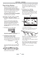
SERVICING - WARNING Disconnect from electricity and gas before servicing. Check appliance is safe when you have finished. Reassemble in reverse order. When replacing leads refer to the wiring diagram. Check operation of timer, ignition, and oven light switches. Servicing Notes When servicing or replacing gas carrying components disconnect from gas before commencing operation and check appliance is gas sound after completion.
SERVICING - WARNING Disconnect from electricity and gas before servicing. Check appliance is safe when you have finished. 4. To Remove a Side Panel 7. To Remove A Thermostat Disconnect from electricity supply. Remove control panel (see 2) and cooktop (see 3). Open the appropriate oven door and remove the oven shelves. Remove control panel (see 2). Pull the cooker forward. Remove the 4 retaining screws for each panel (2 at the front and 2 at the rear).
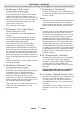
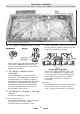
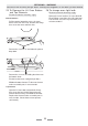
SERVICING - WARNING Disconnect from electricity and gas before servicing. Check appliance is safe when you have finished. top of range with cooktop removed 10. To Change Cooktop Burner Orifice burners. Remove the screw at the front holding the cross support. Slide the support to the right to release in from the rear location. Remove burner cap and head. Remove old jet. Fit new orifice. Note the Wok burner has 2 orifices. Reassemble in reverse order. Check appliance is gas sound.
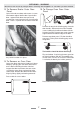
SERVICING - WARNING Disconnect from electricity and gas before servicing. Check appliance is safe when you have finished. 13. To Remove Broiler Outer Door Panel 15. To Change Oven Door Outer Panel Open left hand oven door and remove 2 screws from bottom edge of broiler door. Open broiler door, support broiler door outer panel and remove two screws from top inner face of broiler door. There is a pad of fibre insulation inside the door. Remove the two plastic blanking plugs from the door handles.
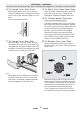
SERVICING - WARNING Disconnect from electricity and gas before servicing. Check appliance is safe when you have finished. 16. To Change Oven Door Catch 18. To Adjust Oven Door Catch Keep Remove outer door panel (see 15). Remove screws ‘B’ holding catch assembly to inner door panel. Fit new catch and reassemble in reverse order. Open oven door, slacken off locknut at base of keep, and screw in or out as required until required fit is obtained. Retighten locking nut. 19.
SERVICING - WARNING Disconnect from electricity and gas before servicing. Check appliance is safe when you have finished. replacement and re-assemble parts in reverse order. Check that the oven operates satisfactorily. panel away. Re-assemble in reverse order. Ensure that the retaining fixings are fully tightened. 21. To Replace the Cooling fan 23. To Remove an Oven fan Element Disconnect from electricity supply. Disconnect from electricity supply.
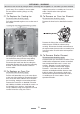
SERVICING - WARNING Disconnect from electricity and gas before servicing. Check appliance is safe when you have finished. 25 To Remove the LH Oven Bottom and Top Elements 26. To change oven light bulb. Disconnect from the electricity supply. Disconnect from the electricity supply. Remove the oven furniture. Unscrew the bulb. Fit an Edison screw fitting 15w 125-130v lamp, FOR OVENS. It must be a special bulb, heat resistant to 300 °C.
SERVICING - WARNING Disconnect from electricity and gas before servicing. Check appliance is safe when you have finished.
Broiler switch block Broiler controller BSB BTC Ignition spark generator Left hand oven switch block Neon indicator light ISG LOS NLI 12 Left hand oven thermostat OTL Right hand top outer element Right hand fan element RBE RFE Right hand fan element RTI Timer clock TCO Thermal cut out TCK RTO Right hand top inner element Right hand oven switch block RSB ROE Right hand oven element Oven light bulb OVL OTR Right hand oven thermostat Oven light switch OLS OFM Oven fan motor Igni
Caution: Label all wires prior to disconnection when servicing controls. Wiring errors can cause improper and dangerous operation. Verify proper operation after servicing. Schematic circuit diagram SERVICING - WARNING Disconnect from electricity and gas before servicing. Check appliance is safe when you have finished.
SERVICING - WARNING Disconnect from electricity and gas before servicing. Check appliance is safe when you have finished. Technical Data This cooker is supplied set for Natural gas. A conversion kit from NG to LP gas is included. INSTALLER: Please leave these instructions with the User. DATA BADGE LOCATION: installation instructions. Inside base of drawer cavity - remove drawer. For removal of drawer see Country of Destination: USA Gas Natural Gas 4.0” W.C Electric 120/240V 60Hz Propane 10.0” W.C.
SERVICING - WARNING Disconnect from electricity and gas before servicing. Check appliance is safe when you have finished.
Aga Ranges LLC 110 Woodcrest Road Cherry Hill NJ 08003 Telephone Number 1-800-633-9200 Email support@aga-ranges.