Dual Fuel Range Service Instructions This book contains many important safety messages. Always read and obey all safety messages. F104650-01 www.aga-ranges.
Contents Servicing Notes 4 1. To Remove the Hand Rail 4 2. To Remove Control Panel 4 3. To Remove the Cooktop 4 4. To Remove a Side Panel 4 5. To Remove Oven Light Switch 5 6. To Remove Electronic Timer 5 7. To Remove a Thermostat 5 8. To Change Broiler Controller 5 9. To Change a Cooktop Tap 5 10. To Change a Cooktop burner orifice 5 11. To Change Cooktop Burner Electrode 5 12. To Remove or Change a Cooktop Burner. 6 13. To Remove Broiler Outer Door Panel 6 14.
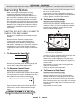
SERVICING - WARNING Disconnect from electricity and gas before servicing. Check appliance is safe when you have finished. Pull the control panel forward and support so that the wires are not strained. Reassemble in reverse order. When replacing leads refer to the wiring diagram. Check operation of timer, ignition, and oven light switches. Servicing Notes When servicing or replacing gas carrying components disconnect from gas before commencing operation and check appliance is gas sound after completion.
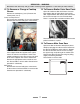
SERVICING - WARNING Disconnect from electricity and gas before servicing. Check appliance is safe when you have finished. 5. To Remove Oven Light Switch 6. To Remove Electronic Timer Remove control panel (see 2). NB The old switch may be destroyed during removal. Remove switch button and old switch from its bezel by gripping the switch body behind the control panel and twisting sharply. The switch bezel can then be removed by folding back its locking wings and pushing forward.
SERVICING - WARNING Disconnect from electricity and gas before servicing. Check appliance is safe when you have finished. 7. To Remove a Thermostat 10. To Change a Cooktop burner orifice Standard burner Remove control panel (see 2) and cooktop (see 3). Open the appropriate oven door and remove the oven shelves. Wok burner RH oven Remove oven roof. Remove the two fixings that secure the thermostat phial cover.
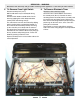
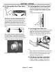
SERVICING - WARNING Disconnect from electricity and gas before servicing. Check appliance is safe when you have finished. 13. To Remove Broiler Outer Door Panel 12. To Remove or Change a Cooktop Burner. Open left hand oven door and remove 2 screws from bottom edge of broiler door. Open broiler door, support broiler door outer panel and remove two screws from top inner face of broiler door. There is a pad of fibre insulation inside the door. Remove the cooktop tray (see 3).
SERVICING - WARNING Disconnect from electricity and gas before servicing. Check appliance is safe when you have finished. 15. To Change Main Oven Door Outer Panel 16. To Change Main Oven Door Catch Remove outer door panel (see 15). Remove screws ‘B’ holding catch assembly to inner door panel. Fit new catch and reassemble in reverse order. Check correct door operation. Remove the two plastic blanking plugs from the door handles.
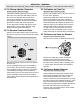
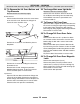
SERVICING - WARNING Disconnect from electricity and gas before servicing. Check appliance is safe when you have finished. 19. To Change Ignition Generator 22. To Replace an Oven Fan Disconnect from electricity supply. Disconnect from electricity supply. Pull cooker forward to gain access to the cover box at the rear of the left hand cooker. Remove the screws securing the cover and lift clear. Pull off all the leads to the generator noting their positions.
SERVICING - WARNING Disconnect from electricity and gas before servicing. Check appliance is safe when you have finished. 25 To Remove the LH Oven Bottom and Top Elements Disconnect from the electricity supply. 26. To change Main oven light bulb. Disconnect from the electricity supply. Remove the oven furniture. Unscrew the bulb. Fit an Edison screw fitting 15w 125-130v lamp, FOR OVENS. It must be a special bulb, heat resistant to 300 °C.
SERVICING - WARNING Disconnect from electricity and gas before servicing. Check appliance is safe when you have finished. 30. To Replace the Cooling fan Disconnect from electricity supply. Remove the cooktop see 3. Disconnect the leads from the fan noting the orientation. Remove the fan from the mounting bracket. Fit the new fan and reassemble in reverse order.
Description Broiler controller BTC 12 Left hand oven switch block Neon indicator light LOS NLI Left hand oven thermostat OTL Oven light bulb Timer clock TCO Thermal cut out TCK RSB Right hand oven switch block ROE Right hand oven element OVL OTR Right hand oven thermostat Oven light switch OLS OFM Oven fan motor Left hand top outer element Left hand fan element LFE LTO Left hand bottom element LBE Left hand top inner element Ignition spark generator ISG LTI Ignition switches
Caution: Label all wires prior to disconnection when servicing controls. Wiring errors can cause improper and dangerous operation. Verify proper operation after servicing. Schematic diagram of the Range Disconnect from electricity and gas before servicing. Check appliance is safe when you have finished.
SERVICING - WARNING Disconnect from electricity and gas before servicing. Check appliance is safe when you have finished. Technical Data This range is supplied set for Natural gas. A conversion kit from NG to LP gas is included. INSTALLER: Please leave these instructions with the User. DATA BADGE LOCATION: Under the Main oven. Remove the plinth by pulling forward (it is held in place by magnetic catches) and pull forward on the sheet metal tag under the center of the oven to swing out the badge plate.
SERVICING - WARNING Disconnect from electricity and gas before servicing. Check appliance is safe when you have finished.
Aga Ranges 110 Woodcrest Road Cherry Hill, NJ 08003 USA 1.866.4AGA.4USA www.aga-ranges.com Email support@aga-ranges.