AGA SIX-FOUR SERIES - DC6 (NATURAL GAS AND PROPANE GAS) OWNERS MANUAL WARNING: If the information in this manual is not followed exactly, a fire or explosion may result causing property damage,personal injury or death. Do not store or use gasoline or other flammable vapors and liquids in the vicinity of this or any other appliance. WHAT DO YOU DO IF YOU SMELL GAS . Do not try to light any appliance. . Do not touch any electrical switch . Do not use any phone in your building. .
CONTENTS SECTION PAGE INSTALLATION SECTION 3 TECHNICAL DATA INSTALLATION FITTING AND PRODUCT DIMENSIONS ELECTRICAL CONNECTION CONNECTING TO GAS LOCATION COOKER STABILITY PRESSURE TESTING LEVELLING AND MOBILITY WHEELS FITTING OF HOTPLATE CASTINGS AND PAN SUPPORTS SPLASHBACK USERS GUIDE 4 5 6 7-8 9 10 11 - 12 12 13 14 - 17 18 19 GENERAL INFORMATION SAFETY PRECAUTIONS AND HINTS PRODUCT VIEW CONTROL PANEL GAS HOTPLATE TO FIT PAN SUPPORTS SETTING UP THE COOKER FOR USE SIMMERING OVEN SIMMERING OVEN RECIPES
Installation Section Remember, when replacing a part on this appliance, use only spare parts that you can be assured conform to the safety and performance specification that we require. Do not use reconditioned or copy parts that have not been clearly authorised by AGA.
TECHNICAL DATA HOTPLATE NATURAL GAS BURNER TYPE MAXIMUM HEAT INPUT BTU’s/hr L.H.F. R.H.F. WOK ULTRA-RAPID RAPID RAPID CENTRE CENTRE FRONT REAR SEMI-RAPID SEMI-RAPID ULTRA-RAPID 6 kW 3.22 kW 3.22 kW 1.91 kW 1.91 kW 5 kW 20,500 11,000 11,000 6,500 6,500 17,000 118 - 118 - 190 - INJECTOR MARKING MAIN 215 SECONDARY V 155 - R.H.R. L.H.R. 155 - PRESSURE POINT POSITION: REAR RH SIDE OF HOTPLATE PRESSURE SETTING: 4” W.G. BURNER IGNITION: H.T.
INSTALLATION CAUTION: THIS INSTALLATION MUST CONFORM WITH LOCAL CODES OR, IN THE ABSENCE OF LOCAL CODES WITH THE NATIONAL FUEL GAS CODE, ANSI Z223.I/NFPA 54 AND NATIONAL ELECTRICAL CODE ANSI/NFPA 70 (IN CANADA CAN/CGA-B149) AND ONLY USED IN A WELL VENTILATED SPACE, READ THESE INSTRUCTIONS BEFORE INSTALLING OR USING THIS APPLIANCE. PRIOR TO INSTALLATION, ENSURE THAT THE LOCAL DISTRIBUTION CONDITIONS (NATURE OF GAS AND GAS PRESSURE) AND THE ADJUSTMENTS OF THE APPLIANCE ARE COMPATIBLE.
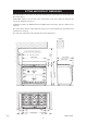
FITTING AND PRODUCT DIMENSIONS Any side wall above the cooker on either side shall be not less than 75mm (3”) horizontally from the cooker (Fig. 1). Combustible surfaces over the top of the cooker must not be closer than 28” and must not exceed 13” in depth. (See Fig. 1). A minimum clearance of 1000mm must be available at the front of the cooker to enable it to be serviced. The cooker must stand on a firm and level surface, we recommend that any soft material such as linoleum is removed.
ELECTRICAL CONNECTION Electric Shock Hazard Electrical Grounding is required on this appliance. Do Not connect to the electrical supply until the appliance is permanently grounded. Disconnect the power to the junction box before making the electrical connection. This appliance must be connected to a grounded, metallic, permanent supply or a grounding connector should be connected to the grounding terminal or wire lead on the appliance. Do Not ground to gas pipe.
ELECTRICAL CONNECTION (continued) ELECTRICAL CONNECTION IS LOCATED AT THE TOP RIGHT HAND SIDE OF THE APPLIANCE, BEHIND SIDE PANEL. DURING INSTALLATION REMOVE THE RIGHT HAND SIDE PANEL TO CONNECT ELECTRICAL SUPPLY. Remove 6 screws securing side panel to gain access to mains terminal. See Fig. 3 for location of cover.
CONNECTING TO GAS CAUTION: ENSURE THAT THE COOKER IS ISOLATED FROM ELECTRIC SUPPLY The cooker can be installed with an approved flexible connection. Supply piping should not be less than 3/8 I/D Flexiline. Connection is made to the 1/2” NPT female threaded elbow located just below the hotplate level on the right hand side of the cooker. Fig. 3 DESN 512639 The gas flexiline connector must be fitted in the shaded area dimensioned in Fig. 3.
LOCATION This appliance must be installed on 1/8” thick Commercial Grade Vinyl composition floor finishing materials or equivalent. The side wall clearance above the hotplate shall be greater than 3”. Surfaces over the top of the range must not be closer than 28” and must not exceed 13” in depth. The vent slots in the back of the top plate (or shroud) must not be obstructed. Note: It is essential that the supply cable is routed away from any hot surfaces i.e. hot flue pipes.
COOKER STABILITY A stability bracket shall be secured firmly to the fabric of the building. For positioning of bracket (See Fig. 3). A safety chain should also be anchored firmly to the wall and cooker to prevent strain on the gas connection, when the cooker is withdrawn for servicing. When fitting a stability bracket and chain refer to Fig. 3, 3A and 3B. Fig. 3A DESN 512638 Ranges must have an anti-tip bracket correctly installed as per these instructions.
POSITION OF GAS BAYONET ON WALL (locate in shaded areas) IMPORTANT: THE GAS SUPPLY CONNECTION AT THE WALL MUST NOT PROJECT OUT FROM THE WALL BY MORE THAN 1 3/4”, SO THAT IT DOES NOT INTERFERE WITH THE BACK OF THE COOKER. Fig. 4 DESN 512640 PRESSURE TESTING The maximum gas inlet pressure to the appliance must not exceed 10” w.g. for NG and 14” for L.P. Gas. The minimum gas inlet pressure at the appliance must not be less than 5” w.g. Natural Gas and 11” w.g. L.P.
LEVELLING AND MOBILITY WHEELS INSTALLATION/LEVELLING The 6-4 Series is designed to stand on a flat and level surface, however, any unevenness may be overcome by adjusting the four levelling feet, one at each corner of the base plate. The adjusting screws are accessed by removing left and right hand hotplate castings (See section ‘To Remove Hotplate Castings - Servicing Section Page 47). To raise the cooker turn screw clockwise, to lower turn screw counter-clockwise. Fig.
FITTING OF HOTPLATE CASTING AND PAN SUPPORTS HOTPLATE CASTINGS 1. Attach earth cable from centre casting to cooker chassis and locate over burner bodies. Repeat for LH and RH castings and that the gaskets are fitted where the outer castings overlap centre castings. Ensure that earth cables are attached. (See Fig. 6A) GRUB SCREW Fig. 6A DESN 512400 2. Secure castings using 8 profiled fixing nuts. DO NOT OVERTIGHTEN. (See Fig. 6B). GASKET Fig.
3. Fit and secure six burner rings using M4 screws on rear left hand, front centre, front right hand and rear right hand burners. Use No.6 3/8 screw on front left hand and centre rear burners. (See Fig. 6C). NOTE: The fitting of LH and centre burners are the same as shown in Fig. 6B. Fig. 6C DESN 512419 4. Position burner caps onto burner bodies. (See Figs. 7A, 7B & 7C) ULTRA RAPID BURNER Fig.
ASSEMBLY OF RAPID AND SEMI-RAPID BURNERS BURNER CAP BURNER HEAD ELECTRODE Fig. 7B DESN 511618 FITTING BURNER CAP - RAPID AND SEMI-RAPID BURNERS BURNER CAP RETAINING LUGS Fig.
5. Fit the pan supports in the following order The pan supports are marked on the underside to correspond to the markings below. The pan supports must locate in the recesses in the hotplate casting. (See Fig. 8A & 8B) Fig. 8A Important It is very important for the performance and reliability of the hob that the pan supports are fitted in accordance with the AGA SIX-FOUR SERIES - DC6 OWNERS MANUAL.
Fig. 8C DESN 512392 A TO ADJUST PAN SUPPORT LEVEL 1. 2. 3. 4. Loosen retaining nut using 8mm spanner (See Fig. 8C). To prevent rocking adjust the pan support foot using 2.5mm allen key. Check pan support is level with opposing pan supports. Retighten retaining nut. HANDRAIL FITTING 1. 2. Position handrail assembly onto locating studs at each end of facia. Ensure the grub screw at each end of the hand rail is facing downwards.
Users Guide 19
GENERAL INFORMATION As responsible manufacturers we take care to make sure that our products are designed and constructed to meet the required safety standards when properly installed and used. IMPORTANT NOTICE: PLEASE READ THE ACCOMPANYING WARRANTY. Any alteration that is not approved by Aga could invalidate the approval of the appliance, operation of the warranty and could affect your statutory rights.
SAFETY PRECAUTIONS AND HINTS 1. Do not store combustible materials, gasoline or other inflammable vapors and liquids near a range cooker. Child Safety Children MUST be taught safe range practices to prevent possible injury. Listed below are some basic practices we recommend you read and follow for safe use of this appliance when children are present. Children are more sensitive to heat than adults, therefore:1. 2. 3. 4. 5.
Fig.
CONTROL PANEL z The GAS HOTPLATE CONTROL KNOBS can only be rotated counter-clockwise from the OFF position. Symbol - Ignition Setting Large Flame Symbol - High Setting Small Flame Symbol - Low Setting (See ‘HOTPLATE’ section). Fig. 11 DESN 512934 A z The BROILER ELEMENT CONTROL KNOB can be rotated in either direction. Clockwise Full on, with both elements on Counter-clockwise Economy grill, centre element only z The OVEN CONTROL KNOBS can only be rotated clockwise from the OFF position.
GAS HOTPLATE z The hotplate has six gas burners: front left - ultra rapid (wok) burner - rated at 6.0 kW rear left and front centre - semi-rapid burners - each rated at 1.91 kW rear right and front right - rapid burner - each rated at 3.22 kW centre rear - ultra rapid burner - rated at 5.0 kW z The semi rapid burners are especially suited for use with small pans and gentle simmering or poaching. z All burners have a set simmer position and are easily adjustable.
IMPORTANT SAFETY CONSIDERATIONS z Simmering aids such as asbestos or mesh mats are not recommended. They can impede burner performance, damage the pan supports and waste fuel. z Commercially available foil spillage aids are unnecessary on this cooker and could effect the combustion. z Some ‘Wok’ cooking pans are unstable. Check with the ‘Wok’ manufacturer before purchasing. z Do not use unstable and mis-shapen pans (e.g. with convex bases) that tilt easily.
TO FIT PAN SUPPORTS Fit the pan supports in the following order. The pan supports are marked on the underside to correspond to the markings below. The pan supports must locate in the recesses in the hotplate casting. Fig. 13A DESN 513712 A Important It is very important for the performance and reliability of the hob that the pan supports are fitted in accordance with the AGA SIX-FOUR SERIES - DC6 OWNERS MANUAL.
SETTING UP THE COOKER FOR USE Before you can use the lower left hand oven of the appliance it will be necessary to set the ‘time of day’ clock. This is a 24 hour clock, and when the power supply is initially switched on, or after an interruption in supply, the clock will show AUTO and 0.00 alternately. Fig. 14 SETTING THE TIME OF DAY 1. Press and hold the MINUTE TIMER and COOK TIME buttons at the same time, (the word AUTO flashes and the 0.
SIMMERING OVEN THE SIMMERING OVEN This is used for long, slow cooking over 6-8 hours, keeping food warm and warming plates for short periods. EXTRA CARE MUST BE TAKEN WHEN WARMING BONE CHINA - USE THE LOWEST SETTING. The slow cooking setting is the area marked between 225ºF - 250ºF on the oven control knob. USING THE SIMMERING OVEN SETTING Points to bear in mind when preparing food. z Do not place dishes directly on to the oven base. Always place onto shelf supplied. See Fig. 17B.
Simmering Oven Simmering Oven • Simmering Oven • Simmering Oven • Simmering Oven • Simmering Oven • IDEAS FOR THE SIMMERING OVEN Many favorite recipes can be adapted for this type of cooking. Check that chosen ovenware will fit into the oven.
Simmering Oven • Simmering Oven • Simmering Oven • Simmering Oven • Simmering Oven • Simmering Oven • Simmering Oven Meal 2 6 - 8 hours cooking Roast Fillet of Lamb Dauphinoise Potatoes Bread and Butter Pudding Recipes Roast fillet of Lamb 900g - 1.25 kg (2-2 1/2 lbs) lamb 1. 2. Season and wrap the lamb in foil. Stand meat on a rack (if possible) over a small shallow tin.
Simmering Oven • Simmering Oven • Simmering Oven • Simmering Oven • Simmering Oven • Simmering Oven • Simmering Oven • Meal 3 6 - 8 hours cooking Ham and Apricot Pie Braised Red Cabbage St. Clements Pudding Recipes Gammon and Apricot Pie 2 ham slices approx 15mm (1/2”) thick 100g (4oz) no-soak dried apricots 25g (1oz) raisins 3 large potatoes, thinly sliced 300ml (1/2 pt) chicken stock 50g (2oz) butter, melted 1. 2. 3. 4. Remove the rind from the ham. Nick the edges and lay them in a shallow dish.
Simmering Oven • Simmering Oven • Simmering Oven • Simmering Oven • Simmering Oven • Simmering Oven • Simmering Oven • Meal 4 Chilli Con Carne Frangipane and Apple Pudding Recipes Chilli Con Carne 450g (1lb) minced beef 1 x 400g (14oz) can tomatoes 1 x 400g (14oz) can kidney beans 1 packet Chilli con carne spice mix 100ml (4 fl oz) water 1. 2. 3. 4. Brown the minced beef in a flame proof casserole dish. Stir in the spice mix. Add beans drained, tomatoes and water. Mix well together.
BROILING OVEN z THE BROILING COMPARTMENT DOOR MUST BE KEPT OPEN WHEN THE BROILER IS ON. z CAUTION: Accessible parts may be hot when the grill is in use. Young children should be kept away. z The very high speed instant broiler is divided into two areas to save energy and to suit individual broiling requirements. z Turn the broiler control clockwise and the whole of the broiling area can be used for large amounts of food.
THE OVENS General z The ovens and broiler compartment are fitted with side and back self-cleaning panels. The roof of the oven is also self-cleaning enamel. z The shelves are designed to be non-tilt. z To remove a shelf, lift clear of the side notches and slide forward. To replace a shelf, insert into the oven with the short prongs at the rear, facing upwards. Slide into position above the side notches then allow to drop down on the runner.
OVEN COOKING GUIDE Cooking Hints z Shelf positions are counted from the bottom. z Put dishes in the centre of the shelf. z When using the fan oven, reduce conventional oven settings by 50ºF - 75ºF and in some cases, cooking time by up to 10 minutes for every hour. z It is important to check that food is piping hot before serving. z You can change the setting and cooking times to suit your tastes. Deep Fat Frying z Do not try to fry too much food at a time, especially frozen food.
Roasting Oven Roasting Oven • Roasting Oven • Roasting Oven • Roasting Oven • Roasting Oven z The right hand upper oven is a conventional oven which means that the heating elements are in the top and under the base of the oven compartment. z The cooking charts are a general guide but times and temperatures may vary according to individual recipes. z The meat sections should be used as a general guide but may vary according to the size, shape of joint on or off the bone.
Roasting Oven • Roasting Oven • Roasting Oven • Roasting Oven • Roasting Oven • Roasting Oven • Roasting Oven • SETTING °F SHELF POSITION APPROXIMATE COOKING TIME Meringue Toppings 275 - 300 1 or 2 45 mins Meringues 210 - 225 2 3 - 4 hours - Turn meringues over as soon as they are set Bread - loaves 425 - 450 1 30 - 45 mins Bread - rolls 425 - 450 2 or 3 15 - 20 mins 375 1 or 2 25 - 35 mins Small Cakes 375 3 20 - 25 mins Victoria Sandwich 350 3 25 - 30 mins Swiss Roll 375 2
Baking Oven • Baking Oven • Baking Oven • Baking Oven • Baking Oven • Baking Oven • z The left hand lower oven is a fan oven, which means that the air is circulated to create an even temperature throughout. In most cases food requires a lower oven temperature when cooked in ovens by approximately 50ºF 75ºF. z The cooking charts are a general guide but times and temperatures may vary according to individual recipes.
• Baking Oven • Baking Oven • Baking Oven • Baking Oven • Baking Oven • Baking Oven • Baking Oven SETTING °F APPROXIMATE COOKING TIME Meringue Toppings 250 45 mins Meringues 175 3 - 4 hours - Turn meringues over as soon as they are set Bread - loaves 275 - 400 30 - 45 mins Bread - rolls 375 - 400 15 - 20 mins 350 25 - 35 mins Small Cakes 325 - 350 20 - 25 mins Victoria Sandwich 300 - 325 25 - 30 mins Swiss Roll 375 - 400 7 - 10 mins 325 20 mins 375 - 400 10 - 15 mins Maderia Ca
THE MINUTE TIMER The minute timer works separately from the time of day clock and can be set to time periods from 1 minute to 23.59 hours. Only a one handed operation is required. SETTING THE MINUTE TIMER 1. Press the MINUTE TIMER button the bell symbol and 0.00 will be displayed. Set the required time by using the plus + and minus - buttons. 2. After 5 seconds the display will go back to showing the time of day, the bell symbol will remain steady and the set time will immediately start to count down.
AUTOMATIC COOKING CONTROL This can be used to set an automatic cooking program in the Baking Oven only. It switches the electricity on and off at the pre-set times. The maximum length of cooking program which can be set is 23 hours and 59 minutes e.g. delay time + cooking time = maximum 23 hours and 59 minutes. Before setting a program check that the clock is telling the correct time of day, and have the following information to hand: z z z The length of time the food needs to cook.
AUTOMATIC COOKING CONTROL (continued) KEY LOCK If this mode is activated, a program can be set, but it will not be function, ie. ON and OFF times will be set, but the timer will not switch the ovens on. TO ACTIVATE KEYLOCK FUNCTION 1. Ensure the timer is in manual mode (no active programs). 2. Hold the MINUTE TIMER button and COOK TIME button simultaneously for approximately 8 seconds. The display will read ON. 3. Press the plus + button. The display reads ‘OFF’ and the key symbol appears.
CLEANING & CARING FOR YOUR COOKER General z Always switch OFF at the mains before cleaning. z Use as little water as possible. z Do not use CAUSTIC CLEANING SOLUTIONS z Do not use a steam cleaner to clean this cooker. z If milk or fruit juice or anything containing acid is spilt on the cooker, wipe it up immediately. z Wipe up any spills as they occur and transfer pans to other burners to continue cooking.
CLEANING & CARING FOR YOUR COOKER COOKER PART AND FINISH CLEANING METHOD Vitreous Enamel Clean with a damp cloth and hot soapy water. Stubborn stains can be removed with mild cream, paste or liquid cleaners, or by gently rubbing with a well moistened, liberally soaped very fine steel wool pads e.g. Brillo. The pan supports, roasting tin and baking tray may OCCASIONALLY be cleaned in a dishwasher.
COOKER PART AND FINISH CLEANING METHOD Heat-Clean Enamel This special enamel has a continuous cleaning action, which works best if a patter of low and high temperature cooking is followed. By using low temperature roasting, excessive fat splashes can be avoided. Should any excessive staining occur, immediately clean the area with hot water containing detergent, and a nylon washingup brush. Resistant stains require the oven to be run at 210ºC for 2 hours.
Oven Shelves - These shelves are designed to slide out STOP ON SHELF MUST PROJECT UPWARDS SHELF STOP AND ANTI -TILT BRACKET DESN 511867 Refit as follows: Locate in guide as above. DESN 511866 Please Note: Shelf slides out to stop position. Fig. 17A Grill Shelf - operates as oven shelves DESN 512411 Fig.
ASSEMBLY OF RAPID AND SEMI-RAPID BURNER BURNER CAP BURNER HEAD ELECTRODE Fig. 18 DESN 511618 FITTING BURNER CAP - RAPID AND SEMI-RAPID BURNER BURNER CAP RETAINING LUGS Fig.
ULTRA-RAPID BURNER Fig.
Servicing Section Remember, when replacing a part on this appliance, use only spare parts that you can be assured conform to the safety and performance specification that we require. Do not use reconditioned or copy parts that have not been clearly authorized by AGA.
SERVICING z COMPLETELY ISOLATE FROM ELECTRIC SUPPLY BEFORE SERVICING. z In the event of your appliance requiring maintenance, please call Aga-Ranges Service or contact your authorized distributor. z Your cooker must only be serviced by a qualified engineer from an authorized distributor. z Do not alter or modify the cooker. z Only the spares specified by the manufacturer are to be fitted.
WARNING: WHEN SERVICING OR REPLACING GAS CARRYING COMPONENTS, DISCONNECT GAS SUPPLY TO APPLIANCE AND AFTER COMPLETION CHECK APPLIANCE FOR GAS SOUNDNESS. WARNING: WHEN SERVICING OR REPLACING COMPONENTS. COMPLETELY ISOLATE THE APPLIANCE FROM THE ELECTRIC SUPPLY AND BEFORE RECONNECTING, CHECK FOR ELECTRICAL SAFETY. A. TO REMOVE HOTPLATE 1. 2. 3. 4. 5. Isolate from electric supply. Remove pan supports and burner caps. (See Fig. 22) Remove burner fixing screws (14) and hotplate fixing nuts (8).
Fig. 24 DESN 512407 B. TO REMOVE SIDE PANELS 1. 2. 3. 4. 5. 6. Isolate from electric supply. Proceed as ‘TO REMOVE HOTPLATE CASTINGS’. Lower the cooker onto the rollers by turning the adjusting feet fully counter-clockwise. NOTE: It may be necessary to disconnect the flexible gas connection to allow the cooker to be withdrawn from between the kitchen units. Roll the cooker slightly forward, unhook the safety chain and disconnect the flexible hose.
D. TO REMOVE HANDRAIL (SEE FIG. 25) 1. 2. Loosen 2 grub screws, one at each end of hand rail (see fig. 25) using 3/32” socket key. Slide handrail forwards, off locating studs. E. TO REMOVE TIMER 1. 2. 3. 4. Isolate from electric supply. Proceed as ‘TO REMOVE HOTPLATE CASTINGS’. Remove fixing screws (4). Two top rear and two lower front of timer housing. The timer assembly can now be lifted upwards sufficiently to disconnect electric cables at rear of timer. (See Fig. 26).
E. TO REMOVE GAS TAPS/IGNITION SWITCHES 1. 2. 3. 4. Isolate from electric and gas supply. Proceed as ‘TO REMOVE HOTPLATE’. Disconnect gas rail feed pipe (19mm nut). (See Fig. 28) Disconnect all gas connections to taps. LH side 5 nuts (5/16”, 9/16” and 3/4”). RH side 4 nuts (9/16” and 3/4”) Remove (10) screws fixing gas rail support panel and gas rail. Disconnect ignition switch cables. Lift away inner facia and move clear, do not stress wires on thermostats. (See Fig. 28).
F. TO REMOVE GRILL REGULATOR 1. 2. 3. 4. 5. 6. Isolate from electric supply. Proceed as ‘TO REMOVE FACIA CASTINGS’. Remove two screws securing control to control mounting panel. Withdraw control and cable taking care not to strain the cables. Disconnect cables from the control. NOTE: Take care to identify terminations. Re-assemble in reverse order. G. TO REMOVE OVEN THERMOSTATS 1. 2. 3. 4. 5. Isolate from electric supply. Proceed as ‘TO REMOVE GRILL REGULATOR’. Remove (7) back panel screws.
I. TO REMOVE ELECTRODES (LHR, CF, RHR, RHF BURNERS) 1. 2. 3. Isolate from electric supply. Proceed as ‘TO REMOVE THE HOTPLATE’. Proceed as ‘TO REMOVE SPARK GENERATOR’ disconnect the appropriate electrode lead. Withdraw clip securing electrode to burner and withdraw lead and electrode (See Fig. 29). Re-assemble in reverse order. 4. 5. Fig. 29 DESN 511649 J. TO REMOVE ELECTRODES (LHF AND CR BURNER) 1. 2. 3. 4. 5. Isolate from electrical supply. Proceed as ‘TO REMOVE HOTPLATE’.
Fig. 31 DESN 512922 K. TO REMOVE OVEN AND GRILL LINERS - SEE FIG. 32 1. 2. Remove LH and RH runners (4 screws per runner). Remove runners and liners. Fig.
L. TO REMOVE ELEMENTS (RH OVENS) 1. 2. 3. 4. 5. 7. Isolate from electrical supply. Proceed as ‘TO REMOVE OVEN AND GRILL LINERS’. Remove oven base panel (1) screw at the rear of the oven. Lift out base panel. Remove oven element fixing screws (2) at the rear of the oven and flex elements to remove from location bracket, pull forwards to expose terminal connections. Remove connection, make sure they do not fall down the back of the appliance.
WIRING DIAGRAM - AGA 6-4 (USA/CAN) APPLIANCE MUST BE COMPLETELY ISOLATED KEY B - BROWN BK - BLACK BL - BLUE Y - YELLOW R - RED V - VIOLET W - WHITE G - GREEN WARNING Electrical Grounding Instructions This appliance is equipped with a (three-prong) (four-prong) grounding plug for your protection against shock hazard and should be plugged directly into a properly grounded receptacle. Do not cut or remove the grounding prong from this plug.
For further advice or information contact your local Aga distributor With Aga’s policy of continuous product improvement, the Company reserves the right to change specifications and make modifications to the appliance described at any time. 110 Woodcrest Road Cherry Hill NJ 08003 800.633.9200 www.aga-ranges.