
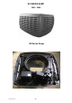
Specifications


FM774/0708 BOOK 2 43
WATER INLET
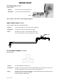
MAGNETIC WATER LEVEL SYSTEM (MWL)
Introduced 2000
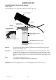
MAGNETIC SENSOR WATER LEVEL SYSTEM (MS)
Introduced 2000-2002
Purpose: Determine water level. Adjustable by holding float shaft and
rotating ball float.
Description: The float assembly is wired in series with the solenoid on the
24v circuit. A schematic wiring diagram of MWL sys tem can be
found on page 20.
FLOAT ASSEMBLY (SP2200)
MWL CONTROL UNIT (SP2210)
Purpose: Determine water level. Adjustable by holding float shaft and
rotating ball float.
Description: This float assembly is connected by a pre-assembled 3 pin
cable directly onto the roof unit. For testing purposes it is
easier to remove this cable from MRU, so testing each compo
nent. It must be remembered when doing this there is no con-
trol over the water level. A schematic wiring diagram of MS
system can be found on page 19.
Notes: A faulty MS board can cause several faults which point to
MRU failure. It is important to be aware of these to avoid
unnecessary MRU replacement.
MS FLOAT ASSEMBLY (SP2200)
MS CONTROL UNIT (SP2212)