AGA DUAL CONTROL Electric Model No. - DC3 Installation Guide REMEMBER: when replacing a part on this appliance, use only replacement parts that you can be assured conform to the safety and performance specification that we require. Do not use reconditioned or copy parts that have not been clearly authorized by AGA. PLEASE READ THESE INSTRUCTIONS BEFORE COMMENCING SITE SURVEY OR INSTALLING THIS APPLIANCE.
CONTENTS SECTION PAGE PRODUCT SAFETY 3 GENERAL NOTES 4 DELIVERY REQUIREMENTS 4 GENERAL INSTALLATION REQUIREMENTS 4 APPLIANCE DIMENSIONS - AGA DC3 5 INSTALLATION 6-7 CONNECTION TO THE POWER SUPPLY - AGA DC3 8 MAINS SUPPLY LOCATION - AGA DC3 9 AGA DC3 HANDRAIL CONNECTION 10 WIRING DIAGRAM - AGA DC3 11 INSTRUCTIONS 12 2
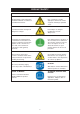
PRODUCT SAFETY MEANING/DESCRIPTION SYMBOL SIGNIFICATION/DESCRIPTION WARNING/CAUTION AVERTISSEMENT An appropriate safety instruction should be followed or caution to a potential hazard exists. Une consigne de sécurité appropriée doivent être suivies ou garde d’un danger potentiel exists. DANGEROUS VOLTAGE TENSION DANGEREUSE To indicate hazards arising from dangerous voltages. Pour indiquer les dangers résultant des tensions dangereuses.
GENERAL NOTES NOTE: THESE INSTALLATION INSTRUCTIONS SHOULD BE LEFT WITH THE RANGE AND THE USER TO RETAIN FOR FUTURE REFERENCE. Before installation of an AGA can be made, the site is inspected for suitability by an authorized AGA distributor and corrected where necessary to conform with local or regional electrical codes. DELIVERY REQUIREMENTS The AGA DC3 arrives on 1 pallet. There must be access to the kitchen to manipulate a foot print of 39 9/16” (1005mm) x 29 1/8” (740mm).
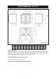
RANGE DIMENSIONS - AGA DC3 RH SIDE VIEW FRONT VIEW LH SIDE VIEW PLAN VIEW MINIMUM WALL POSITION MINIMUM WALL POSITION Fig. 1 A B C mm 987 951 913 pouces 38 7/8 37 3/8 35 7/8 D E F G DESN 516297 H 680 1388 760 1145 698 26 3/4 54 5/8 29 7/8 45 1/8 27 1/2 J K L 116 10 634 4 9/16 3/8 25 Range Dimensions When surveying for a range installation the actual clearance required for the ‘body’ of the appliance should be increased by 3/8” (10mm) beyond the figures quoted above.
INSTALLATION Range Base or Hearth It is essential that the base or hearth on which the range stands should be level and be capable of supporting the total weight of the range. The base of the built-in AGA plinth must be level and sit above finished floor height for service access. Plinth The front plinth cover is removable and must not be obstructed by flooring or tiles. If necessary the range must be raised by the thickness of the tiles to ensure the plinth can be removed.
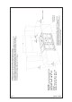
Fig. 2 DESN 516668 7 CABINETS MUST NOT EXCEED 13” PROJECTED DEPTH ABOVE THE RANGE. DIM ‘D’ TO BE NOT LESS THAN THE NORMAL WIDTH OF THE RANGE.
CONNECTION TO THE POWER SUPPLY - AGA DC3 Electric Shock Hazard Rating plate is located behind removable plinth, see Fig. 4, Page 9 Electrical grounding is required on this appliance. DO NOT connect to the electrical supply until the appliance is permanently grounded. This appliance must be connected to a grounded metallic permanent supply or a grounding connector should be connected to the grounding terminal or wire lead on the appliance.
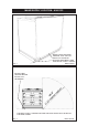
MAINS SUPPLY LOCATION - AGA DC3 MAINS CABLE FED FROM CONTROL TRAY LEFT OR RIGHT EXIT THROUGH DUCTING DEPENDENT UPON POSITION OF SUPPLY SOCKET DESN 516643 Fig. 3 RATING LABEL LOCATED BEHIND PLINTH, PULL TO REMOVE THE MAINS SUPPLY CONNECTION AND ISOLATION POINT MUST BE WITHIN THE ZONE SHOWN Fig.
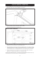
AGA DC3 HANDRAIL CONNECTION 1. Fit the handrail bracket over the fixing stud located on the top plate. Lock into position by tightening the grub screw nearest the appliance. (See Fig. 5). Fig. 5 2. DESN 516883 Next the handrail, endcaps and handrail require assembly. Slide the handrail through the handrail brackets. AGA DC3 HANDRAIL CONNECTION Fig. 6 DESN 516880 3.
WIRING DIAGRAM - AGA DC3 Fig.
INSTRUCTIONS Hand the Users Guide to the user for retention and instruct in the safe operation of the range. Advise the user that, for continued efficient and safe operation of the range, servicing is carried out at intervals recommended by the AGA distributor. When replacing a part on this range, use only replacement parts that you can be assured conform to the safety and performance specification that we require. Do not use reconditioned or copy parts that have not been clearly authorised by AGA.
For further advice or information contact your local AGA Specialist With AGA Marvel’s policy of continuous product improvement, the Company reserves the right to change specifications and make modifications to the appliance described and illustrated at any time Supplied by AGA Marvel 1260 E. Van Deinse St. Greenville, MI, 48838 Business (616) 754-5601 Fax (616) 754-9690 Toll Free Telephone 800-223-3900 www.agamarvel.