AGA DUAL CONTROL Model No. - DC3 & DC5 Installation Guide PLEASE READ THESE INSTRUCTIONS BEFORE COMMENCING SITE SURVEY OR INSTALLING THIS APPLIANCE.
CONTENTS SECTION PAGE PRODUCT SAFETY 3 GENERAL NOTES 4 DELIVERY REQUIREMENTS 4 GENERAL INSTALLATION REQUIREMENTS 4 APPLIANCE DIMENSIONS - AGA DC3 5 APPLIANCE DIMENSIONS - AGA DC5 6 INSTALLATION 7-8 CONNECTION TO THE POWER SUPPLY - AGA DC3 9 POWER SUPPLY - HOT CUPBOARD AGA DC5 10 MAINS SUPPLY LOCATION - AGA DC3 11 MAINS SUPPLY LOCATION - AGA DC5 12 HOTCUPBOARD INSTALLATION 13 - 19 WIRING DIAGRAM - AGA DC3 20 WIRING DIAGRAM - AGA DC5 21 INSTRUCTIONS 22 2
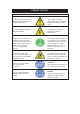
PRODUCT SAFETY MEANING/DESCRIPTION SYMBOL SIGNIFICATION/DESCRIPTION WARNING/CAUTION AVERTISSEMENT An appropriate safety instruction should be followed or caution to a potential hazard exists. Une consigne de sécurité appropriée doivent être suivies ou garde d’un danger potentiel exists. DANGEROUS VOLTAGE TENSION DANGEREUSE To indicate hazards arising from dangerous voltages. Pour indiquer les dangers résultant des tensions dangereuses.
GENERAL NOTES NOTE: THESE INSTALLATION INSTRUCTIONS SHOULD BE LEFT WITH THE RANGE AND THE USER TO RETAIN FOR FUTURE REFERENCE. DELIVERY REQUIREMENTS The AGA DC3 arrives on 1 pallet. The AGA DC5 (Hotcupboard Option) arrives on 2 pallets. There must be access to the kitchen to manipulate a foot print of 39 9/16” (1005mm) x 29 1/8” (740mm).
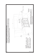
APPLIANCE DIMENSIONS - AGA DC3 RH SIDE VIEW FRONT VIEW LH SIDE VIEW PLAN VIEW MINIMUM WALL POSITION MINIMUM WALL POSITION Fig.
APPLIANCE DIMENSIONS - AGA DC5 Fig. 2 DESN 516561 A B C mm 1478 948 910 58 1/ 35 7/8 ins 37 3/8 D E F 680 1388 760 26 3/4 54 5/8 29 7/8 G H J K L 1145 698 116 10 634 45 1/8 27 1/2 4 5/8 3/8 25 Range Dimensions When surveying for a range installation the actual clearance required for the ‘body’ of the appliance should be increased by 3/8” (10mm) beyond the figures quoted above.
INSTALLATION Range Base or Hearth It is essential that the base or hearth on which the range stands should be level and be capable of supporting the total weight of the range. The base of the built-in AGA plinth must be level and sit above finished floor height for service access. Plinth The front plinth cover is removable and must not be obstructed by flooring or tiles. If necessary the range must be raised by the thickness of the tiles to ensure the plinth can be removed.
Fig. 3 DESN 51668 8 CABINETS MUST NOT EXCEED 13” PROJECTED DEPTH ABOVE THE RANGE. DIM ‘D’ TO BE NOT LESS THAN THE NORMAL WIDTH OF THE RANGE.
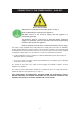
CONNECTION TO THE POWER SUPPLY - AGA DC3 Electric Shock Hazard Rating Plate is located behind removable plinth, see Fig. 4. Electrical Grounding is required on this appliance. DO NOT connect to the electrical supply until the appliance is permanently grounded. This appliance must be connected to a grounded metallic permanent supply or a grounding connector should be connected to the grounding terminal or wire lead on the appliance.
POWER SUPPLY - HOTCUPBOARD (AGA DC5) The hotcupboard attachment requires an independent single phase supply. It has a maximum load of 6 amps, protected by an appropriate branch circuit supply. 110/120V 60 Hz FLEXIBLE CORD and PLUG PARALLEL TYPE (NEMA 5-15P). The appliance when installed must be electrically grounded in accordance with local or regional codes. An electrical socket must be provided within 5 feet of the LH side of the appliance and easily accessible for the user to disconnect.
MAINS SUPPLY LOCATION - AGA DC3 MAINS CABLE FED FROM CONTROL TRAY LEFT OR RIGHT EXIT THROUGH DUCTING DEPENDENT UPON POSITION OF SUPPLY SOCKET Fig. 3 DESN 516643 RATING LABEL LOCATED BEHIND PLINTH, PULL TO REMOVE THE MAINS SUPPLY CONNECTION AND ISOLATION POINT MUST BE WITHIN THE ZONE SHOWN Fig.
MAINS SUPPLY LOCATION - AGA DC5 (HOTCUPBOARD OPTION) HOTCUPBOARD POWER SUPPLY MAINS CABLE FED FROM CONTROL TRAY LEFT OR RIGHT EXIT THROUGH DUCTING DEPENDENT UPON POSITION OF SUPPLY SOCKET Fig. 5 DESN 516562 RATING LABEL LOCATED BEHIND PLINTH, PULL TO REMOVE, THE MAINS SUPPLY CONNECT POINT MUST BE WITHIN THE ZONES SHOWN Fig.
HOTCUPBOARD INSTALLATION NOTE: The AGA DC5 hotcupboard should arrive with the top plate in a jacked up position. This is to allow the complete range to be slid onto its plinth when alongside the AGA DC3 without the top plates clashing. The hotcupboard top plate should then be wound down to its correct height once the appliance is in its final position. 1. Detach hotcupboard from plinth by removing two screws and tongue bracket from plinth (See Fig.
2. Position the plinth alongside the AGA Dual Control leaving no gap between the two plinths (See Fig. 8). Check with a spirit level that the plinth level is correct, and also check height differential between the hotcupboard plinth and Dual Control plinth is correct 3/8” (11mm). If necessary, use shims in each corner to level the plinth. HOTCUPBOARD PLINTH BASE 3/8” +1 11mm - 0 HEIGHT DIFFERENTIAL Fig. 8 DESN 516276 3.
4. Run a straight edge along the front of the AGA Dual Control plinth, to ensure the front face of both plinths sit squarely against the straight edge. (See Fig. 10) When satisfied both plinths sit squarely, jacking screws can be tightened until they just make contact with the AGA Dual Control plinth, and locking screws can now be tightened. USE STRAIGHT EDGE ACROSS BOTH PLINTHS TO ENSURE PLINTHS ARE ALIGNED SQUARELY Fig. 10 DESN 516551 5.
6. Slide hotcupboard onto plinth until rear tongue bracket engages fully into rear of base slot, (See Fig. 12). Ensure the appliance is aligned squarely with the plinth then proceed to engage the front tongue bracket into the slot on the underside of the base plate. Once satisfied that the front tongue bracket is engaged fully lock it into place by tightening the two M6 screws fully. Ensure that the electrical cable does not come into contact with oven vent pipe from the AGA DC3. Fig. 12 DESN 516552 7.
8. Using the stay rod nut adjusting tool, carefully lower the top plate adjusting nuts until the top plate sits at the required height, making sure that the top sits level and matches the height of the AGA DC3. (See Fig. 14). Fig. 14 DESN 516555 9. Fit the handrail bracket over the fixing stud located on the top plate. Lock into position by tightening the grub screw nearest the appliance. (See Fig. 15). Fig.
10. Next the handrail, endcaps and handrail require assembly. Slide the handrail through the handrail brackets. AGA DC3 HANDRAIL CONNECTION Fig. 16 DESN 516880 11. On 5 oven ranges, fit allthread stud into the insert located in the one end of the handrail, then feed the handrail through the bracket (ensuring that the allthread stud is protruding from the right hand side of the hotcupboard handrail) and screw the handrails together. (See Fig. 17). AGA DC5 HANDRAIL CONNECTION Fig.
12. Once the handrail assembly is located squarely, lock the handrail in position by winding in the grub screws on the underside of each handrail bracket. 13. Once the handrails are locked in position, fit the handrail endcaps. The endcaps should be carefully pushed into place until they sit flush with the outside face of each bracket (a light smear of lubricant such as, washing up liquid on the end cap ‘O’ rings may ease fitment. 14.
WIRING DIAGRAM - AGA DC3 Fig.
WIRING DIAGRAM - AGA DC5 (HOTCUPBOARD OPTION) COLOUR KEYS/COLLEURS CAUTION: LABEL ALL WIRES PRIOR TO DISCONNECTION, WHEN SERVICING CONTROLS WIRING ERRORS CAN CAUSE IMPROPER AND DANGEROUS OPERATION. VERIFY PROPER OPERATION AFTER SERVICING ATTENTION: ETIQUETEZ TOUS LES CABLES AVANT DE LES DEBRANCHER LORS DE LES BRANCHER LORS DE L’ENTRETIEN DES COMMANDES. DES ERREURS DE CABLAGE PEUVENT ENTRAINER UN FONCTIONNEMENT INCORRECT ET DANGEREUX. VERIFIEZ QUE L’ APPAREIL FONCTIONNE CORRECTEMENT APRES L’ENTRETIEN. Fig.
INSTRUCTIONS Hand the Users Guide to the user for retention and instruct in the safe operation of the range. Advise the user that, for continued efficient and safe operation of the range, servicing is carried out at intervals recommended by the AGA distributor. When replacing a part on this range, use only replacement parts that you can be assured conform to the safety and performance specification that we require. Do not use reconditioned or copy parts that have not been clearly authorised by AGA.
For further advice or information contact your local AGA Specialist With AGA Marvel’s policy of continuous product improvement, the Company reserves the right to change specifications and make modifications to the appliance described and illustrated at any time Supplied by AGA Marvel 1260 E. Van Deinse St. Greenville, MI, 48838 Business (616) 754-5601 Fax (616) 754-9690 Toll Free Telephone 800-223-3900 www.agamarvel.