
Use and Care Guide


43
INSTALLATION
Check the appliance is electrically safe when you have nished.
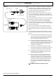
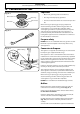
To Install the new orices; see Table 15.1 for orice details.
Insert the new orice into the open end of the rubber tube
which is attached to the socket wrench. Screw into the orice
carrier as far as possible and lift the socket wrench away
(Fig. 15.4).
Remove the rubber tubing from the socket wrench and
tighten all of the orices.
Replace the rings on the burners. Screw in the hexagon
headed venturi to make tting the burners easier. DO NOT
tighten yet.
When all the burner bases and venturis have been tted
tighten the venturi nuts.
Valve adjustment
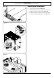
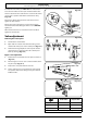
Removing the control panel
1. Pull o all the control knobs.
2. Open both oven doors and remove the xing screws
underneath and top rear of the control panel (Fig. 15.5).
3. Pull forward and gently lift the control panel. Rest the
control panel on a cloth to protect the control panel
from any damage (Fig. 15.5).
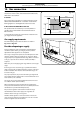
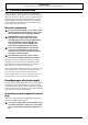
Bypass screw adjustment
1. Remove the 4 screws from the cover plate as shown in
(Fig. 15.6)
2. Turn the bypass screw on each control clockwise all the
way till it stops (Fig. 15.7).
3. Replace the cover plate with the 4 screws.
4. Fit the control panel, over and push the control panel
into position. Replace the xing screws you removed.
Ret the knobs.
Table 15.1
ArtNo.0102-0011 - Screwing
the control valve bypass screw
100
140
180
220
0
1
33
22
1
0
00000
100
140
180
220
0
0
Fig. 15.4
Fig. 15.5
Fig. 15.6
Fig. 15.7
Natural Gas Propane Gas*
Center burner
205 118
Large Burners
150 99
Right front burner
112 68
* Jets and labels can be found in the accompanying bag