
Hanwood - Manual

PRE-INSTALLATION
Before using the stove for the first time all remaining
stickers must be removed, all accessories must be
removed from the ashpan, check if any items have
become dislodged during transport.
CHIMNEY/FLUES
The stove is a radiant room heater and must be con-
nected to a proper type chimney/flue for safe evac-
uation of products of combustion. The chimney/flue
must have a diameter of 150mm or equivalent cross
sectional area. Never connect to a smaller size
chimney/flue. Do not connect to a chimney/flue
serving another appliance. A minimum chimney/flue
height of 4.5 metres from the flue spigot on the stove
to the top of the chimney/flue is required. The chim-
ney/flue must be constructed of material capable of
withstanding a soot fire in the chimney/flue which
can lead to temperatures of 1000 degrees. The
chimney/flue must be constructed with sockets
uppermost so that when condensation occurs within
the pipe, it should flow down the inside of the pipe
that it will transfer to the inner of the next pipe with-
out seeping through the joints. The chimney/flue
should provide a minimum continuous draught of 12
pascals, if the stove is connected into an existing
chimney where the refractory flue liner is of a diam-
eter in excess of 200mm the chimney should be
relined using a flexible flue liner. The flexi liner is not
recommended to be connected directly to the appli-
ance, there should be a minimum of 0.6 meters rigid
flue pipe coming off the appliance. The chimney/flue
should be designed to allow for cleaning of the
stove, use pipes with cleaning doors where neces-
sary.
Avoid the use of 90 degree elbows, use 2 x 45
o
bends instead. Horizontal runs of flue pipe should
be avoided, where it is unavoidable the maximum
permitted horizontal run is 150mm. The
chimney/flue must have the necessary clearance
distance from combustible material. The chimney
termination must be free of any obstructions, see
requirements under Approved Document J, avail-
able to download at www.planningportal.gov.uk
For guidance when installing new chimney systems
or relining existing chimneys please refer to BS EN
15287:
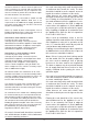
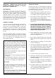
DOWN DRAUGHTS
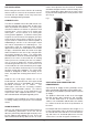
However well designed constructed and positioned,
the satisfactory performance of the flue can be
adversely affected by down draught caused by near-
by hills, adjacent tall buildings or trees. These can
deflect wind to blow directly down the flue or create
a zone of low pressure over the terminal. A suitable
anti-down draught terminal or cowl will usually effec-
tively combat direct down blow but no cowl is likely
to prevent down draught due to a low pressure zone.
(See Fig.1)
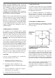
Direction of wind
Direction of wind
Direction of wind
Pressure zone
Pressure zone
Suction zone
Suction zone
Pressure zone
Suction zone
Fig 1
3
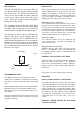
VENTILATION AND COMBUSTION AIR
REQUIREMENTS
A permanent air supply must be provided in accor-
dance with Building Regulation ADJ and BS 8303.
Alternatively it is possible to provide a direct external
air supply.
The product is fitted with a with an air inlet spigot
that will accept a pipe of diameter 120 externally.
The air duct fitted must be of minimum diameter
120mm, non combustible and ducted to the outside
in a manner that will not effect the performance of
the stove.
No sharp bends and a maximum duct length of 10
metres is permissible. Where the duct terminates on
an external wall ensure that there is no risk of block-
age with leaves or accidental placement of items,
ensure there is no risk of ingress of moisture or