48” Dual Fuel Range Owner’s Guide User & Installation Instructions READ THESE INSTRUCTIONS FULLY BEFORE USE SAVE THESE INSTRUCTIONS FOR FUTURE REFERENCE U110649 - 03d
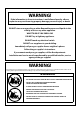
WARNING! If the information in these instructions is not followed exactly, a fire or explosion may result causing property damage, personal injury or death. DO NOT store or use gasoline or other flammable vapors and liquids in the vicinity of this or any other appliance. WHAT TO DO IF YOU SMELL GAS DO NOT try to light any appliance. DO NOT touch any electrical switch. DO NOT use any phone in your building. Immediately call your gas supplier from a neighbor’s phone. Follow the gas supplier’s instructions.
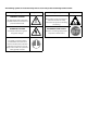
The following symbols are related to Safety and are used on the product and throughout this manual. Meaning / Description WARNING / CAUTION An appropriate safety instruction should be followed or caution to a potential hazard exists. Symbol ! Meaning / Description HEAVY This product is heavy and reference should be made to the safety instructions for provisions of lifting and moving. DANGEROUS VOLTAGE DISCONNECT MAINS SUPPLY To indicate hazards arising from dangerous voltages.
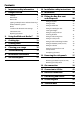
Contents 1. Important safety information 1 10. Installation safety instructions 24 2. Range overview 5 11. Installation 26 Cooktop 5 Wok burner 6 Wok cradle 6 12.
1. Important safety information Read all instructions before using this appliance. Save these instructions for future reference. If the range is installed near a window, proper precautions should be taken to prevent curtains from blowing over the burners. Have your appliance properly installed and grounded by a qualified technician. The installation must conform with local codes or in the absence of local codes in accordance with the National Fuel Gas Code, ANSI Z223.
Use dry oven gloves when applicable – using damp gloves might result in steam burns when you touch a hot surface. NEVER operate the range with wet hands. Teach them not to play with controls or any other part of the range. NEVER store items of interest to children in the cabinets above a range or on backguard of a range; children climbing on the range to reach them could be seriously injured. Important safety notice and warning DO NOT use the oven for storage.
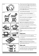
Cooktop burners Ovens Quality of flames On Natural Gas the burners’ flames should be a blueish color with, at most, a slight yellowish fringe. Use care when opening door. nn Let hot air and steam escape before removing or nn replacing food. On Propane gas the flames may be “softer”. The cooktop burner flames may have a slight yellowish tip. NEVER heat unopened food containers. Pressure nn build up may make container burst and cause injury.
Take care when touching range, to minimize the nn possibility of burns, always be certain that the Foods for frying should be as dry as possible. Frost on frozen foods or moisture on fresh foods can cause hot fat to bubble up and over the sides of the pan. Carefully watch for spills or overheating of foods when frying at high or medium high temperatures. NEVER try to move a pan of hot fat, especially a deep fry pan. Wait until the fat is cool.
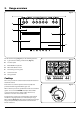
2. Range overview DocAUS.020-0004 - Overview - 110DF - Elan Fig. 2.1 A E 0 0 0 0 0 0 0 0 1 0 1 2 2 100 220 180 100 220 3 140 3 180 140 B C F D G The 48” dual fuel range (Fig. 2.1) has the following features: A. 5 gas burners including 1 wok burner (Fig. 2.2) B. A control panel C. Glide Out Broiler System™ D. Main multi-function oven E. Interlocking cast iron grates F. Convection oven G. Storage drawer Fig. 2.2 Cooktop 0 0 0 0 0 0 0 0 1 0 1 ArtNo.
Fig. 2.4 When you release the control knob, if the burner goes out, the Flame Supervision Device (FSD) has not been bypassed. Turn the control knob to the OFF position and wait for one minute before you try again, this time making sure to hold in the control knob for slightly longer. 0 Adjust the flame height to suit by turning the knob counterclockwise (Fig. 2.4). On this range the low position is beyond high, not between high and off.
We recommend a minimum wok pan of 13 3/16” (335 mm). The cradle should be used on the wok burner only. When you fit the cradle, make sure that it is supported properly on a burner grate and the wok is sitting level in the cradle (Fig. 2.12). Fig. 2.12 The cradle will get very hot in use – allow plenty of time for it to cool before you pick it up. Igniting cooktop burners without electricity Fig. 2.13 If there is a power failure, the cooktop burners can be lit with a match. 1.
Ovens Convection This function operates the fan and the heating element around it. An even heat is produced throughout the oven, allowing you to cook large amounts quickly. Please refer to (Fig. 2.1). References to ‘left-hand’ and ‘right-hand’ ovens apply as viewed from the front of the appliance. The left-hand oven is a multi-function oven, while the righthand oven is a convection oven.
Conventional (Top and Base Heat) This function combines the heat from the top and base elements. It is particularly suitable for roasting and baking pastry, cakes and biscuits. Food cooked on the top shelf will brown and crisp faster than on the lower shelf, because the heat is greater at the top of the oven than at the base, as in ‘Fan Assisted’ function. Similar items being cooked will need to be swapped around for even cooking.
Operating the ovens Fig. 2.14 0 Operating the multi-function oven 0 °F 150 450 200 400 The multi-function oven has two controls: a function selector and a temperature setting knob (Fig. 2.14). 2. Turn the function selector control to a cooking function. Fig. 2.15 shows the control set for convectional oven cooking. 3. Turn the oven temperature knob to the temperature required (Fig. 2.15). 250 350 Function control 1.
Flammable materials may explode and result in fire nn or property damage. 2 To fit the telescopic shelf runners With the runner arm in the closed position locate the opening of the upper rear slot onto the side support (Fig. 2.22). DO NOT locate any further than the opening at this point. 1. Lift the front of the runner arm to locate the front slot against the side support (Fig. 2.22). 2. Push the runner arm towards the rear of the oven.
3. Using the Glide-out Broiler™ DocAUS.020-0004 - Overview - 110DF - Elan Fig. 3.1 Fig. 3.2 Nearest to the element Middle High Middle Low Furthest from the element Four grill height positions refer to Fig. 3.5 Fig. 3.3 Fig. 3.4 To switch on both element To switch on the right half element Fig. 3.5 Four grill height positions Nearest to the element Middle High 180o Cooking suggestions Furthest from the element 180o Middle Low 180o 180o 1. Nearest to the element – Toast, steak. 2.
4. Cooking tips When the oven is on, DO NOT leave the door open for longer than necessary, otherwise the knobs may get very hot. Cooking with a multi-function oven REMEMBER: not all modes are suitable for all food types. The oven cooking times given are intended for a guide only. • Always leave a ‘‘finger’s width’’ between dishes on the same rack. This allows the heat to circulate freely around them.
5. Cooking table DocNo.031-0004 - Cooking table - electric & fan single cavity The oven control settings and cooking times given in the table below are intended to be used as a guide only. Individual tastes may require the temperature to be altered to provide a preferred result. Food is cooked at lower temperature in a fan oven than in a conventional oven. When using recipes, reduce the fan oven temperature by 25 °F and the cooking time by 5-10 minutes.
6. Cleaning your range Essential information Fig. 6.1 Before thorough cleaning, turn off the circuit nn breaker. Allow the range to cool. After cleaning remember to switch on the circuit nn breaker before using the range. NEVER use paint solvents, caustic cleaners, nn biological powders, bleach, chlorine based bleach ArtNo.311-0030 - Burner head fitting cleaners, coarse abrasives or salt. DO NOT mix different cleaning products – they may nn react together with hazardous results.
Stainless steel main top Fig. 6.4 Lift away pots or pans from main top. Remove grates from spillage area and carefully place in a sink of warm soapy water. Wipe loose debris from main top. Avoid using any abrasive cleaners including cream cleaners on brushed stainless steel surfaces. For best results use a liquid detergent cleaner. Rinse with cold water and thoroughly dry with a clean, soft cloth. Make sure all parts are dry before repositioning.
Glide-out broiler™ Fig. 6.5 Before you remove any of the broiler parts for nn cleaning, make sure that they are cool, or use oven gloves. Wash the broiler pan, trivet and broiler tray in hot soapy water. Alternatively, wash the broiler pan in a dishwasher. After broilling meats or any foods that soil, leave to soak for a few minutes in the sink immediately after use. Stubborn particles may be removed from the trivet by using a nylon brush. 1. Fig. 6.
Cleaning table Regular cleaning is recommended (Table 6.1). For easier cleaning, wipe up any spillages immediately. For enamelled surfaces use a cleaner that is approved for use on vitreous enamel.
7. Troubleshooting All servicing and repairs must be carried out by a nn qualified service engineer. We DO NOT recommend corrosive or caustic nn cleaners as these may damage your range. Ignition or cooktop burners faulty The knobs get hot when I use the oven, can I avoid this? Is the power on? Yes, this is caused by heat rising from the oven, and heating them up. DO NOT leave the oven door open.
Oven not coming on Fig. 7.1 Is the power on? If not there may be something wrong with the power supply. Is the range supply on at the circuit breaker? Have you set a cooking function? ArtNo.320-0006b -Mercury oven door hinge adjustment Oven temperature getting hotter as the range gets older If turning the knob down has not worked or only worked for a short time then you may need a new thermostat. This should be changed by a qualified service engineer.
8. Installation Instructions WARNING! If the information in these instructions is not followed exactly, a fire or explosion may result causing property damage, personal injury or death. DO NOT store or use gasoline or other flammable vapors and liquids in the vicinity of this or any other appliance. WHAT TO DO IF YOU SMELL GAS DO NOT try to light any appliance. DO NOT touch any electrical switch. DO NOT use any phone in your building. Immediately call your gas supplier from a neighbor’s phone.
The following symbols are related to Safety and are used on the product and throughout this manual. Meaning / Description WARNING / CAUTION An appropriate safety instruction should be followed or caution to a potential hazard exists. Symbol Meaning / Description HEAVY ! This product is heavy and reference should be made to the safety instructions for provisions of lifting and moving. DANGEROUS VOLTAGE DISCONNECT MAINS SUPPLY To indicate hazards arising from dangerous voltages.
INSTALLATION Check the appliance is electrically safe and gas sound when you have finished. 9. Service and parts Firstly, please complete the appliance details below and keep them safe for future reference – this information will enable us to accurately identify the particular appliance and help us to help you. Filling this in now will save time and inconvenience if you later have a problem with the appliance. It may also be of benefit to keep your purchase receipt with this leaflet.
INSTALLATION Check the appliance is electrically safe when you have finished. 10. Installation safety instructions Improper installation, adjustment, alteration, nn service or maintenance can cause injury or property Regulations Installation of this range must conform with local nn codes, or in the absence of local codes, with the damage. Refer to this manual. For assistance or additional information, consult a qualified engineer. National Fuel Gas Code, ANSI Z223.1/NFPA.54, latest edition.
INSTALLATION Check the appliance is electrically safe when you have finished. Converting to propane gas This appliance is supplied set for natural gas. A conversion kit for Propane gas is supplied with the range. If the appliance is to be converted this must be done before installation. The conversion must be performed by a qualified LP gas installer. See the ‘Conversion’ section at the back of this installation manual for more details.
INSTALLATION Check the appliance is electrically safe when you have finished. 11. Installation You will need the following equipment to complete the range installation satisfactorily: Additional materials you may need: • Multimeter (for electrical checks). 1. Gas line shut-off valve. 2. Pipe joint sealant or UL-approved pipe thread tape with Teflon* that resists action of natural and LP gases. 3. Flexible metal appliance connector (½’’ I.D.).
INSTALLATION Check the appliance is electrically safe when you have finished. Positioning the range Fig. 11.1 Fig. 11.1, Fig. 11.2 and Fig. 11.3 show the minimum recommended distance from the range to nearby combustible surfaces (see Table 11.1). A We recommend a gap of no more than 3/16” (5 mm) (see Table 11.1) either side of the appliance for moving the range. It must be possible to move the range in and out for cleaning and servicing.
INSTALLATION Check the appliance is electrically safe when you have finished. Fig. 11.4 The depth of the range is 28 7⁄16 " (723 mm) overall (Fig. 11.4). 46 5/16 (1177 mm) If the range is near a corner of the kitchen, a clearance of 3 ½” (90 mm) is required to allow the oven doors to open (Fig. 11.5). The actual opening of the doors is slightly less but this allows for some protection of your hand as you open the door.
INSTALLATION Check the appliance is electrically safe when you have finished. 12. Fitting the flue, flue vent and side panels Fitting the knobs 1. Checking the parts: Gently push-fit the control knobs onto the spindles. Flue Flue Vent Fan Assembly Control knobs x 9 Fitting the flue 1. Remove the four screws from the broiler flue opening (Fig. 12.1). 2. Present the removable flue up to broiler flue opening.
INSTALLATION Check the appliance is electrically safe when you have finished. Fitting the cooling fan box Fig. 12.3 1. Remove the six screws where the cooling fan box will be fixed Fig. 12.3. 2. The shape of the molex plug should match the socket. Gently connect the molex plug to the molex connector socket Fig. 12.4. 3. The cooling fan has two tabs which connects to the slots underneath the flue vent. Gently align the cooling fan box tabs to the slots underneath the flue vent Fig. 12.5. 4.
INSTALLATION Check the appliance is electrically safe when you have finished. Fitting the side panel rear retaining brackets Checking the parts: Side panel rear retaining brackets A052064 - Right-hand A052067 - Left-hand Side panels A051761 - Right-hand A051759 - Left-hand Obscuring Trim Side Panel x2 Q050718 Bottom Panel (Toe kick) Color matched to range Bottom Panel (Toe kick) Front Mounting Brackets Q050877 - Left-hand Q050878 - Right-hand Screws supplied 2x Machine Screw 2x Self-Tapping Screw 1.
INSTALLATION Check the appliance is electrically safe when you have finished. Fitting the obscuring trims Fig. 12.9 1. Located near the front on each side of the range there are three screws. Loosen the top and bottom screws (Fig. 12.9). 2. Slide the trim onto the screws and tighten to secure. Fitting the side panels 1. Loosen the screw in the flue vent (Fig. 12.10). 2. Inside the top of the side panel top are two tabs.
INSTALLATION Check the appliance is electrically safe when you have finished. Fitting the front mounting brackets 1. Open the right-hand oven door and pull the drawer out to its furthest point. 2. Push the ends of the plastic clips (Fig. 12.13 and Fig. 12.14) to release the catches holding the drawer to the side runners. At the same time pull the drawer forward and away from the side runners. Fig. 12.13 For safety’s sake make sure the drawer runners are nn out of the way. 3. 4.
INSTALLATION Check the appliance is electrically safe when you have finished. Fig. 12.17 Fitting the bottom panel (toe kick) Side panel Toe kick Bottom panel Pin Nylon Locating washer Side view of the front base Fig. 12.18 Side panel Toe kick Bottom panel Side view of the front base Fig. 12.19 Fig. 12.20 Side panel Toe kick Bottom panel 34 1. Tilt the bottom of the panel slightly to locate the lower slots onto the washers (Fig. 12.17). Now rotate the panel to fit over the pins (Fig. 12.18). 2.
INSTALLATION Check the appliance is electrically safe when you have finished. Fitting the drawer 1. To fit the drawer, pull the side rails fully out (Fig. 12.21). 2. Carefully move the drawer back between the rails and rest it on the side rails. 3. At each side, hold the front of the drawer and pull the side rail forward so that the clips click into position, holding the drawer to the side rails (Fig. 12.22). Fig. 12.21 Make sure the inner rail is pulled forwards Fig. 12.
INSTALLATION Check the appliance is electrically safe when you have finished. Fitting the restraint chain and antitip device Fig. 12.23 Restraint chain Rigid pipe of the appliance 1. A range using a flexible gas connector must be secured with a suitable restraint chain and anti-tip device. 2. When fitting the restraint chain it should be kept as short as is practicable and fixed firmly to the rigid pipe at the top, right-hand, rear of the range, when viewed from the front (Fig. 12.23).
INSTALLATION Check the appliance is electrically safe when you have finished. 13. Removing the side panels DISCONNECT THE ELECTRICAL SUPPLY. Fig. 13.1 You will need the following equipment to remove the side panels: • Cross-head screwdriver • Flat head screwdriver • Allen keys (provided in pack). Removing the storage drawer 1. Pull the drawer out to its furthest point. 2. Push the ends of the plastic clips (Fig. 13.1 and Fig. 13.2) to release the catches holding the drawer to the side runners.
INSTALLATION Check the appliance is electrically safe when you have finished. Removing the side panels Fig. 13.5 Fig. 13.6 Flue Vent Nylon Retaining washer Side Panel Side panel bracket Fig. 13.7 bk 38 1. Loosen one screw in the vent (Fig. 13.5). 2. Push forward the side panel so that it moves away from the flue vent and the retaining washer (Fig. 13.6). 3. Inside the top of the side panel top are two tabs. Move the side panel up and away from the range (Fig. 13.7).
INSTALLATION Check the appliance is electrically safe when you have finished. 14. Gas connection Installation of this range must conform with local codes or, in the absence of local codes, with the National Fuel Gas Code, ANSI Z223.1-latest edition. Fig. 14.1 11 ¼” Area accessible through drawer In Canada The range must be installed in accordance with the current CGA Standard CAN/CGA-B149 – Installation Codes for Gas Burning Appliances and Equipment and/or local codes.
INSTALLATION Check the appliance is electrically safe when you have finished. Connect the range to the gas supply Fig. 14.3 Flexible connector Adaptor Shut off the main gas supply valve before disconnecting the old range and leave it off until the new hookup has been completed. Don’t forget to relight the pilot on other gas appliances when you turn the gas back on.
INSTALLATION Check the appliance is electrically safe when you have finished. When using test pressures greater than ½ psi (3.5 kPa) to pressure test the gas supply system of the residence, disconnect the range and individual shut-off valve from the gas supply piping. The appliance must be isolated from the gas supply piping system by closing its individual manual shut-off valve during any pressure testing of the gas supply piping system at test pressures equal to or less than 1/2 psi (3.5 kPa).
INSTALLATION Check the appliance is electrically safe when you have finished. 15. Conversion to LP Gas Important Fig. 15.1 • Observe all governing codes and ordinances. Burner head • The range must be properly grounded. Burner ring • Save these instructions for the local electrical inspector’s use. Brass Venturi Burner Base When servicing or replacing gas carrying components disconnect from gas before commencing operation and check appliance is gas sound after completion.
INSTALLATION Check the appliance is electrically safe when you have finished. To Install the new orifices; see Table 15.1 for orifice details. Fig. 15.4 Insert the new orifice into the open end of the rubber tube which is attached to the socket wrench. Screw into the orifice carrier as far as possible and lift the socket wrench away (Fig. 15.4). Remove the rubber tubing from the socket wrench and tighten all of the orifices. Replace the rings on the burners.
INSTALLATION Check the appliance is electrically safe when you have finished. Reassemble Fig. 15.8 1. If you have lifted the maintop, carefully lower it onto the range. The burners are protected against the burner flames going out by Flame Supervision Devices (FSD’s). 2. Take care when lowering the maintop to locate the FSD sensor probes (Fig. 15.8) in their holes in the cook top and the burner bases. 3. Refit the control panel and the knobs. Gas regulator adjustment Fig. 15.
INSTALLATION Check the appliance is electrically safe when you have finished. Stick on labels Complete the conversion label (kit number A060048) and stick it next to the ratings label inside the drawer cavity to indicate the gas the appliance is now set for (Fig. 15.12). This appliance was converted on K085791 month -day -year To gas with kit No *by Also, stick the “NOW ADJUSTED FOR LP GAS” label in a similar position. Q042326 Fig. 15.
INSTALLATION Check the appliance is electrically safe when you have finished. 16. Electrical connection Have your appliance properly installed and grounded by a qualified technician. The installation must conform with local codes or in the absence of local codes in accordance with the National Fuel Gas Code, ANSI Z223.1/NFPA 54 or, in Canada, the Natural Gas and Propane Installation Code, CSA B149.1 and in addition the National Electrical Code NFPA 70 or the Canadian Electric Code, CSA C22.1.
INSTALLATION Check the appliance is electrically safe when you have finished. Fig. 16.1 Recommended electrical outlet location When connecting using a NEMA 14-50R receptacle, if possible position it so it can be accessed through the opening at the rear of the drawer cavity (Fig. 16.1). Alternate location within the shaded area in (Fig. 16.2). The distance between the back of the range and the wall is approximately 4” (10.6 cm). Plug the range power cord into a properly grounded wall receptacle.
INSTALLATION Check the appliance is electrically safe when you have finished. 17. Final fitting and checks Fitting the interlocking grates Fig. 17.1 Please note that the Continuous Grates supports are handed, and may prevent the centre pan supports from fitting correctly. There is a small indent in the rear of each of the outer supports. This indent should be towards the outer edge of the range (Fig. 17.1). Checks Cooktop check Refer to “Range Overview” and check operation of each burner in turn.
18.
19. Technical data INSTALLER: Please leave these instructions with the user. DATA BADGE LOCATION: Inside base drawer of cavity. Remove the drawer (see Overview > Storage for details). COUNTRY OF DESTINATION: USA, Canada, Mexico. Connections ArtNo280-0090 Drawer Cavity & Badges Electric Supply 240 V 60 Hz Electric Rating 240V (2 Wire + N + Grd), 60Hz, 7.4 kW Branch Circuit Protection 35 A Connection Type NEMA 14-50 P Maximum total electric load 240 V (including oven fans, lights, etc.): 7.
CONSUMER WARRANTY ENTIRE PRODUCT – LIMITED ONE YEAR WARRANTY AGA warrants the replacement or repair of all parts, including gas components of this range cooker which prove to be defective in material or workmanship, with the exception of the painted or porcelain enamel finish or plated surfaces, for one year from the date of original purchase. Such parts will be repaired or replaced at the option of AGA without charge, subject to the terms and conditions set out below.
Manufactured in the UK for: AGA Marvel 1260 E. VanDeinse St. Greenville, MI 48838 Business (616) 754-5601 Fax (616) 754-9690 Toll Free Telephone 800-223-3900 www.aga-ranges.