48 Dual Fuel Owner’s Guide User & Installation Instructions U110649 - 01
WARNING! If the information in these instructions is not followed exactly, a fire or explosion may result causing property damage, personal injury or death. DO NOT store or use gasoline or other flammable vapors and liquids in the vicinity of this or any other appliance. WHAT TO DO IF YOU SMELL GAS DO NOT try to light any appliance. DO NOT touch any electrical switch. DO NOT use any phone in your building. Immediately call your gas supplier from a neighbor’s phone. Follow the gas supplier’s instructions.
Contents 1. Important Safety Information 1 2. Range Overview 5 3. Cooking Tips 13 4. Cooking Table 14 5. Cleaning Your Range 15 6. Troubleshooting 19 7. Service and Spares 21 8. Installation 22 9. Fitting the Flue, Flue Vent and Side Panels 26 10. Removing the Side Panels 34 11. Gas Connection 36 12. Conversion to LP Gas 38 13. Electrical Connection 42 14. Final Fitting 45 15. Circuit Diagram 46 16.
1. Important Safety Information Have your appliance properly installed and grounded by a qualified technician. The installation must conform with local codes or in the absence of local codes in accordance with the National Fuel Gas Code, ANSI Z223.1/NFPA 54 or, in Canada, the Natural Gas and Propane Installation Code, CSA B149.1 and in addition the National Electrical Code ANSI/NFPA No. 70 or the Canadian Electric Code, CSA C22.1-02. Storage should not be installed directly above a range.
To avoid risk of electrical shock, personal injury, nn or death, make sure your range has been properly substances, including benzene, formaldehyde and soot, due primarily to the incomplete combustion of natural gas or liquid petroleum (LP) fuels. Properly adjusted burners will minimize incomplete combustion. DO NOT touch cooktop burners or areas near burners. Exposure to these substances can also be minimized by properly venting with an open window or using a ventilation fan or hood.
Use the Right Size Pan Placement of Oven Racks This appliance is equipped with burners of different sizes. Use utensils with flat bottoms. DO NOT use unstable pans and position the handles away from the edge of the cooktop. Make sure the flames are under the pans. It’s not safe to let the flames burn up the sides of the pan; the handle may get too hot. ALWAYS place oven racks in desired location while nn oven is cool.
When an oven is on, DO NOT use the top of the flue (the round holes along the back of the range) for warming plates, dishes, drying dish towels or softening butter. Always keep combustible wall coverings or curtains etc. a safe distance away from your range. DO NOT spray aerosols in the vicinity of the range nn while it is in use. When using an electrical appliance near the cooktop, be sure that the cord of the appliance does not come into contact with the cooktop.
2. Range Overview DocAUS.020-0004 - Overview - 110DF - Elan Fig. 2.1 A E 0 0 0 0 0 0 0 0 1 180 0 1 2 2 100 220 100 220 3 140 3 180 140 B C F D G The 48” dual fuel range (Fig. 2.1) has the following features: Fig. 2.2 0 0 0 0 0 0 0 0 1 2 2 100 180 100 220 3 140 3 180 5 gas burners including 1 wok burner (Fig. 2.2) B. A control panel C. Glide Out Broiler System™ D. Main multi-function oven E. Interlocking cast iron grates F. Convection oven G.
When you release the control knob, if the burner goes out, the FSD has not been bypassed. Turn the control knob to the OFF position and wait for one minute before you try again, this time making sure to hold in the control knob for slightly longer. Fig. 2.4 0 Adjust the flame height to suit by turning the knob counterclockwise (Fig. 2.4). On this range the low position is beyond high, not between high and off.
cradle should be used on the wok burner only. When you fit the cradle, make sure that it is supported properly on a burner grate and the wok is sitting level in the cradle (Fig. 2.12). Fig. 2.12 The cradle will get very hot in use – allow plenty of time for it to cool before you pick it up. Igniting Cooktop Burners without Electricity If there is a power failure, the cooktop burners can be lit with a match. Fig. 2.13 1.
Ovens Convection cooking is particularly suitable for batch baking on several shelves at one time and is a good ‘all-round’ function. It may be necessary to reduce the temperature by approximately 25 °F/10°C for recipes previously cooked in a conventional oven. References to ‘left-hand’ and ‘right-hand’ ovens apply as viewed from the front of the appliance. The left-hand oven is a multi-function oven, while the righthand oven is a convection oven.
Function Browning Use This function uses the element in the top of the oven only. It is a useful function for the browning or finishing of pasta dishes, vegetables in sauce, To thaw small items in the oven without heat. A full cooking function, even heat throughout, great for baking. Defrost Convection Convection broiling and lasagna For best results, the item to be browned should be hot before switching to the top element. Broil meat and fish with door closed.
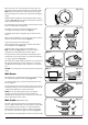
Accessories Fig. 2.21 Fig. 2.22 Fig. 2.23 Fig. 2.24 Oven Shelves The range is supplied with the following: • 2 standard shelves (Fig. 2.21) • 1 drop shelf (Fig. 2.22) • 2 telescopic shelves with runners (Fig. 2.23) • 2 sets of side supports (Fig. 2.24) The oven shelves are retained when pulled forward but can be easily removed and refitted.
Fig. 2.25 2 To Fit the Telescopic Shelf Runners 1 3 1. With the runner arm in the closed position locate the opening of the upper rear slot onto the side support (Fig. 2.25). DO NOT locate any further than the opening at this point. 2. Lift the front of the runner arm to locate the front slot against the side support (Fig. 2.25). 3. Push the runner arm towards the rear of the oven. The catch at the front will lift and drop to secure the runner arm in place (Fig. 2.25).
Storage The bottom drawer is for storing cooking utensils. To open, simply push the drawer in and release. Flammable materials should not be stored in an oven, the range storage drawer or near the cooktop burners. This includes paper, plastic and cloth items, such as cookbooks, plasticware and towels, as well as flammable liquids. Do not store explosives, such as aerosol cans, on or near the appliance. Flammable materials may explode and result in fire nn or property damage.
3. Cooking Tips When the oven is on, DO NOT leave the door open for longer than necessary, otherwise the knobs may get very hot. Cooking with a Multi-function Oven REMEMBER: not all modes are suitable for all food types. The oven cooking times given are intended for a guide only. • Always leave a ‘‘finger’s width’’ between dishes on the same rack. This allows the heat to circulate freely around them.
4. Cooking Table DocNo.031-0004 - Cooking table - electric & fan single cavity The oven control settings and cooking times given in the table below are intended to be used AS A GUIDE ONLY. Individual tastes may require the temperature to be altered to provide a preferred result. Food is cooked at lower temperature in a convection oven than in a conventional oven. When using recipes, reduce the convection oven temperature by 25°F (10°C) and the cooking time by 5-10 minutes.
5. Cleaning Your Range Essential Information Before thorough cleaning, turn off the circuit breaker. Allow the range to cool. After cleaning remember to switch on the circuit breaker before using the range. NEVER use paint solvents, caustic cleaners, nn biological powders, bleach, chlorine based bleach cleaners, coarse abrasives or salt. DO NOT mix different cleaning products – they may nn react together with hazardous results. Recommended cleaning materials are shown in Table 5.1.
Stainless Steel Main Top Fig. 5.1 Lift away pots or pans from main top. Remove grates from spillage area and carefully place in a sink of warm soapy water. Wipe loose debris from main top. Avoid using any abrasive cleaners including cream cleaners on brushed stainless steel surfaces. For best results use a liquid detergent cleaner. Rinse with cold water and thoroughly dry with a clean, soft cloth. Make sure all parts are dry before repositioning. ArtNo.
Glide-out Broiler™ Fig. 5.5 Before you remove any of the broiler parts for nn cleaning, make sure that they are cool, or use oven gloves. Wash the broiler pan, trivet and broiler tray in hot soapy water. Alternatively, wash the broiler pan in a dishwasher. After broilling meats or any foods that soil, leave to soak for a few minutes in the sink immediately after use. Stubborn particles may be removed from the trivet by using a nylon brush. Fig. 5.
Cleaning Table Cleaners listed (Table 5.1) are available from supermarkets or electrical retailers as stated. For enamelled surfaces use a cleaner that is approved for use on vitreous enamel. Regular cleaning is recommended. For easier cleaning, wipe up any spillages immediately.
6. Troubleshooting We DO NOT recommend corrosive or caustic nn cleaners as these may damage your range. Hotplate ignition or cooktop burners faulty Is the power on? The knobs get hot when I use the oven, can I avoid this? Are the sparker (ignition electrode) or burner holes blocked by debris? Yes, this is caused by heat rising from the oven, and heating them up. DO NOT leave the oven door open. Are the burner heads correctly located? See the section entitled ‘Cleaning’.
Oven not coming on Fig. 6.1 Is the power on? If not there may be something wrong with the power supply. Is the range supply on at the circuit breaker? Have you set a cooking function? Oven temperature getting hotter as the range gets older ArtNo.320-0006b -Mercury oven door hinge adjustment If turning the knob down has not worked or only worked for a short time then you may need a new thermostat. This should be changed by a service person.
INSTALLATION Check the appliance is electrically safe and gas sound when you have finished. 7. Service and Parts Service and Parts Firstly, please complete the appliance details below and keep them safe for future reference – this information will enable us to accurately identify the particular appliance and help us to help you. Filling this in now will save time and inconvenience if you later have a problem with the appliance. It may also be of benefit to keep your purchase receipt with this leaflet.
INSTALLATION Check the appliance is electrically safe when you have finished. 8. Installation Regulations Installation Safety Instructions Installation of this range must conform with local codes, or in the absence of local codes, with the National Fuel Gas Code, ANSI Z223.1/NFPA.54, latest edition. Improper installation, adjustment, alteration, nn service or maintenance can cause injury or property damage. Refer to this manual.
INSTALLATION Check the appliance is electrically safe when you have finished. Location of the Range Additional materials you may need: Do not locate the range where it may be subject to strong drafts. Any openings in the floor or wall behind the range should be sealed. Make sure the openings around the base of the range that supply fresh air for combustion and ventilation are not obstructed by carpeting or woodwork. 1. Gas line shut-off valve. 2.
INSTALLATION Check the appliance is electrically safe when you have finished. Positioning the Range 1 3/16” 30 mm min Fig. 8.1 and Fig. 8.2 show the minimum recommended distance from the range to nearby surfaces. Fig. 8.1 13/16” 30 mm min 31 ½” 800 mm min The range should not be placed on a base. Above hotplate surround should be level with, or above, any adjacent work surface.
INSTALLATION Check the appliance is electrically safe when you have finished. When Fitting Between Kitchen Cabinets Fig. 8.4 We recommend that you either: Fit the range so that any cabinet doors are at least 5” (127 mm) behind the range door fronts. Note that this may require an infill piece behind the range. We recommend a gap of 48” (1218 mm) between units to allow for moving the range. DO NOT box the range in – it must be possible to move the range in and out for cleaning and servicing. A.
INSTALLATION Check the appliance is electrically safe when you have finished. 9. Fitting the Flue, Flue Vent and Side Panels Checking the Parts: Flue Fig. 9.1 Flue Vent Flue Fan Assembly Control knobs x 9 Fig. 9.2 Fitting the Knobs 1. Gently push-fit the control knobs onto the spindles. Fitting the Flue 1. Remove the four screws from the broiler flue opening (Fig. 9.1). 2. Present the removable flue up to broiler flue opening.
INSTALLATION Check the appliance is electrically safe when you have finished. Fitting the Cooling Fan Box Fig. 9.4 1. Remove the six screws where the cooling fan box will be fixed Fig. 9.4. 2. The shape of the molex plug should match the socket. Gently connect the molex plug to the molex connector socket Fig. 9.5. 3. The cooling fan has two tabs which connects to the slots underneath the flue vent. Gently align the cooling fan box tabs to the slots underneath the flue vent Fig. 9.6. 4.
INSTALLATION Check the appliance is electrically safe when you have finished. Fitting the Side Panel Rear Retaining Brackets Checking the Parts: Side panel rear retaining brackets A052064 - Right-hand A052067 - Left-hand Side panels A051761 - Right-hand A051759 - Left-hand 1. Located at the bottom left and right rear corner of the range, remove the two screws (Fig. 9.9). 2. Fit the left and right retaining brackets to the base frame and refit and tighten the screws (Fig. 9.9).
INSTALLATION Check the appliance is electrically safe when you have finished. Fitting the Side Panels 4. 1. Loosen the screw in the flue vent (Fig. 9.11). 2. Inside the top of the side panel top are two tabs. Connect these tabs into the cut-outs in the top edge of the range (Fig. 9.12). 3. Slide the side panel back so that the side panel bracket in the base connects to the rear retaining washer and the slotted tab at the top rear connects onto the screw in the flue vent (Fig. 9.13).
INSTALLATION Check the appliance is electrically safe when you have finished. Fitting the Front Mounting Brackets 1. Open the left-hand oven door and pull the drawer out to its furthest point. 2. Push the ends of the plastic clips (Fig. 9.14 and Fig. 9.15) to release the catches holding the drawer to the side runners. At the same time pull the drawer forward and away from the side runners. For safety’s sake make sure the drawer runners are nn out of the way. 3.
INSTALLATION Check the appliance is electrically safe when you have finished. Fitting the Bottom Panel (Toe kick) 1. Tilt the bottom of the panel slightly to locate the lower slots onto the washers (Fig. 9.17). Now rotate the panel to fit over the pins (Fig. 9.18). 2. Using the two screws and allen key supplied, loosely fit the bottom panel onto the mounting brackets (Fig. 9.20). DO NOT tighten at this stage. 3. Adjust the bottom panel to set the gap between the side panels and doors equally (Fig. 9.
INSTALLATION Check the appliance is electrically safe when you have finished. Fitting the Drawer 1. To fit the drawer, pull the side rails fully out (Fig. 9.21). 2. Carefully move the drawer back between the rails and rest it on the side rails. 3. At each side, hold the front of the drawer and pull the side rail forward so that the clips click into position, holding the drawer to the side rails (Fig. 9.22). Fig. 9.21 Make sure the inner rail is pulled forwards Fig. 9.
INSTALLATION Check the appliance is electrically safe when you have finished. Fitting the Restraint Chain and Anti-Tip Device Fig. 9.23 Restraint chain Rigid pipe of the appliance 1. A range using a flexible gas connector must be secured with a suitable restraint chain and anti-tip device. 2. When fitting the restraint chain it should be kept as short as is practicable and fixed firmly to the rigid pipe at the top, right-hand, rear of the range, when viewed from the front (Fig. 9.23).
INSTALLATION Check the appliance is electrically safe when you have finished. 10. Removing the Side Panels Removing the Bottom Panel (Plinth/Toekick) You will need the following equipment to remove the side panels: • Cross-head screwdriver • Flat head screwdriver • Allen keys (provided in pack). Removing the Storage Drawer 1. Pull the drawer out to its furthest point. 2. Push the ends of the plastic clips (Fig. 10.1 and Fig. 10.2) to release the catches holding the drawer to the side runners.
INSTALLATION Check the appliance is electrically safe when you have finished. Removing the Side Panels 1. Loosen one screw in the vent (Fig. 10.5). 2. Push forward the side panel so that it moves away from the flue vent and the retaining washer (Fig. 10.6). 3. Inside the top of the side panel top are two tabs. Move the side panel up and away from the range (Fig. 10.7). Fig. 10.5 Fig. 10.
INSTALLATION Check the appliance is electrically safe when you have finished. 11. Gas Connection Installation of this range must conform with local codes or, in the absence of local codes, with the National Fuel Gas Code, ANSI Z223.1-latest edition. Fig. 11.1 9 ¾” Area accessible through drawer In Canada The range must be installed in accordance with the current CGA Standard CAN/CGA-B149 – Installation Codes for Gas Burning Appliances and Equipment and/or local codes.
INSTALLATION Check the appliance is electrically safe when you have finished. Connect the Range to the Gas Supply When using test pressures greater than ½ psi (3.5 kPa) to pressure test the gas supply system of the residence, disconnect the range and individual shut-off valve from the gas supply piping. Shut off the main gas supply valve before disconnecting the old range and leave it off until the new hookup has been completed.
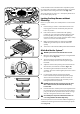
INSTALLATION Check the appliance is electrically safe when you have finished. 12. Conversion to LP Gas Important Fig. 12.1 • Observe all governing codes and ordinances. Burner head • The range must be properly grounded. Burner ring • Save these instructions for the local electrical inspector’s use. Brass venturi Burner base When servicing or replacing gas carrying components disconnect from gas before commencing operation and check appliance is gas sound after completion.
INSTALLATION Check the appliance is electrically safe when you have finished. To Install the new orifices; see Table 12.1 for orifice details. Fig. 12.4 Insert the new orifice into the open end of the rubber tube which is attached to the socket wrench. Screw into the orifice carrier as far as possible and lift the socket wrench away (Fig. 12.4). Remove the rubber tubing from the socket wrench and tighten all of the orifices. Replace the rings on the burners.
INSTALLATION Check the appliance is electrically safe when you have finished. Reassemble 1. If you have lifted the maintop, carefully lower it onto the range. The burners are protected against the burner flames going out by Flame Supervision Devices (FSD’s). 2. Take care when lowering the maintop to locate the FSD sensor probes (Fig. 12.8) in their holes in the cook top and the burner bases. 3. Refit the control panel and the knobs. Fig. 12.8 Gas Regulator Fig. 12.
INSTALLATION Check the appliance is electrically safe when you have finished. Stick on Labels Fig. 12.14 Complete the conversion label (kit number A060048) and stick it next to the ratings label inside the drawer cavity to indicate the gas the appliance is now set for (Fig. 12.14). Q042326 This appliance was converted on K085791 month -day -year To gas with kit No *by Also, stick the “NOW ADJUSTED FOR LP GAS” label in a similar position.
INSTALLATION Check the appliance is electrically safe when you have finished. 13. Electrical Connection Have your appliance properly installed and grounded by a qualified technician. The installation must conform with local codes or in the absence of local codes in accordance with the National Fuel Gas Code, ANSI Z223.1/NFPA 54 or, in Canada, the Natural Gas and Propane Installation Code, CSA B149.1 and in addition the National Electrical Code ANSI/NFPA No. 70 or the Canadian Electric Code, CSA C22.1-02.
INSTALLATION Check the appliance is electrically safe when you have finished. Fig. 13.3 Terminal Block Connecting if the Supplied Cord and Plug is not Suitable Terminal Clamp To remove the electrical connection cover (Fig. 13.1), remove the 4 screws (Fig. 13.2). Red Black 4-Wire Conduit Installation White Earth Post Neutral Post Green 1. Disconnect the supplied power cord from the terminal block, ground and neutral posts.
INSTALLATION Check the appliance is electrically safe when you have finished. 5. Attach the ground strap to the neutral and earth terminal post supplied on the cooker back plate (Fig. 13.9). Tighten the fixings to 3 - 4 Nm (2.20 - 2.95 ft lb). 6. Connect the power cord wire to the terminal block and tighten to 3 - 4 Nm (2.20 - 2.95 ft lb). 7. Tighten the strain relief making sure the wires of the supply cord are installed correctly (Fig. 13.7). 8. Replace the electrical connection cover. 9.
INSTALLATION Check the appliance is electrically safe when you have finished. 14. Final Fitting Fitting the Interlocking Grates Fig. 14.1 Please note that the Continuous Grates supports are handed, and may prevent the centre pan supports from fitting correctly. There is a small indent in the rear of each of the outer supports. This indent should be towards the outer edge of the range (Fig. 14.1). Cooktop Check Check each cooking zone in turn. Be sure to use pans of the correct size and material.
15.
16. Technical Data INSTALLER: Please leave these instructions with the user. DATA BADGE LOCATION: Inside base drawer of cavity. Remove the drawer (see Overview > Storage for details). COUNTRY OF DESTINATION: USA, Canada. Connections Electric ArtNo280-0090 Drawer Cavity & Badges 240 V 60 Hz Gas ½” NPT at rear right-hand side Dimensions Overall height minimum 3515/16” (91cm) maximum 367/8” (93.7cm) Overall width 35½” (90cm); see ‘Positioning of Range’.
Notes 48
AGA Marvel 1260 E. VanDeinse St. Greenville, MI 48838 Business (616) 754-5601 Fax (616) 754-9690 Toll Free Telephone 800-223-3900 www.aga-ranges.