
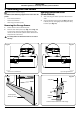
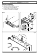
Use and Care Guide


40
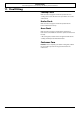
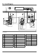
12. Circuit Diagram
Code Code
C1 Right-hand oven thermostat
C2 Right-hand oven switch block
C3 Right-hand oven element
C4 Right-hand oven fan motor
D1 Cooling fan motor
D2 Fan connector plug
F Neon
G Thermal cut-out
Code Description
A1 Broiler Thermostat
A2 Broiler Controller
A3 Broiler Elements
B1 Left-hand oven thermostat
B2 Left-hand oven switch block
B3 Left-hand bottom element
B4 Left-hand oven top outer element
B5 Left-hand oven top inner element
B6 Left-hand oven fan element
B7 Left-hand oven fan motor
Code
Colour
b Blue
br Brown
bk Black
or Orange
r Red
v Violet
w White
y Yellow
gr Grey
6
5
4
7
8
2
1
3
P2
P1
P3
P4
P5
P6
P7
P8
P028728
4
3
2
1
P4
P2
P1
P3
P033458
4
3
2
1
4
3
2
1
P4
P2
P1
P3
P033458
4
3
2
1
P1
4 2
4a P2
S2 S1
P029549
1 2
P026819
1 2
P026819
Induction Unit
b
bk
gy
r
v
or
y
gy
y
r
bk
r
bk
v
v
v
br
br
br
or
b
b b
b
w
or
y
gy
w
or
v
brbr
br
br
r
or
w
y
v
w
w
v
r
r
r
r rr r
bk
r
bk
bk
gy
gy
gy
gy
or
or
or
bk
v
r
r
w
w
w
bk
bk
bk
r
r
r
r
r
gy
v
b
b
r
466
3 12
bk
v
5
4 5
1 2
3
bk
bk
bk
r r
r
r
bk
bk
bk
r
r
r
D1
C3
C4
G
A3
A1
A2
C1
B2
B1
F FF F
N
L2
L1
H
B3
B4
B5
B6
B7
G
C2
D2
H
J
J
LH Oven Control
RH Oven Control
Broiler Control
Code Description
A1
Broiler Thermostat
A2
Broiler Controller
A3
Broiler Elements
B1
Left-hand oven thermostat
B2
Left-hand oven switch block
B3
Left-hand bottom element
B4
Left-hand oven top outer element
B5
Left-hand oven top inner element
B6
Left-hand oven fan element
B7
Left-hand oven fan motor
Code Description
C1
Right-hand oven thermostat
C2
Right-hand oven switch block
C3
Right-hand oven element
C4
Right-hand oven fan motor
D1
Cooling fan motor
D2
Fan connector plug
F
Neon
G
Thermal cut-out
H
Induction Unit
J
Induction Connection Block
Code Color
b
Blue
br
Brown
bk
Black
or
Orange
r
Red
v
Violet
w
White
y
Yellow
gy
Grey