
User Guide

INSTALLATION
Check the appliance is electrically safe and gas sound when you have nished.
35
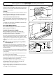
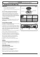
ArtNo.350-0012 - Securing the plinth
Seal the Openings
Seal any openings in the wall behind the range and in the
oor under the range when hookups are completed.
IMPORTANT: When all connections are completed make
sure the ow of combustion and ventilation air to the range
is unobstructed.
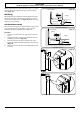
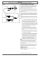
Leveling
Place the range in its intended position taking care not to
twist it within the gap between the kitchen units as damage
may occur to the range or the units. Install the oven racks
in the oven. Check for levelness by placing a level or a cup,
partially lled with water, on one of the oven grids. If using a
spirit level, take two readings with the level placed diagonally
rst in one direction and then the other.
The front feet and rear rollers can be adjusted to level the
range. To adjust the height of the rear of the cooker, use a ½”
(13 mm) spanner or socket wrench to turn the adjusting nuts
at the front bottom corners of the cooker. To set the front feet
turn the bases to raise or lower.
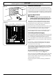
Final Fitting
Installing the Toe Kick
Remove the 3 screws for the toe kick mounts along the front
bottom edge of the range (Fig.7-30). Fasten the toe kick
using these screws (alternative color screws can be found in
the loose parts pack).
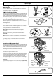
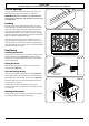
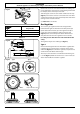
Fitting the Grates
Make sure that the grates are in the correct position and
seated properly (Fig.7-31).
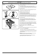
To Fit the Storage Drawer
Slide the inner side rails out until fully extended (Fig.7-32).
Lift the drawer at its sides and locate one of the drawer rails
(approximately ½” (13 mm) onto an inner side rail (Fig.7-33).
Rotate the drawer to locate the remaining drawer rail onto
the opposite inner side rail.
Carefully slide the drawer back into the cavity. Some
resistance will be felt as the drawer rails locate fully onto the
inner side rails.
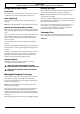
Refitting the Oven Door
To ret the door, slide the hinges back into their slots. Rotate
the locking ‘U’ clips back to t onto the hinges.
Fig.7-31
Fig.7-30
Make sure the inner
rail is forwards
Fig.7-33
Fig.7-32
1/2" (13 mm)
Approx.