Professional 90 Dual Fuel User Guide & Installation & Service Instructions U110246 - 01
Contents 1. Before You Start... 2. 3. 1 6.
1. Before You Start... Read all instructions before using this appliance. Save these instructions for future reference. Many plastics will burn and most are damaged by heat. Keep plastic items away from parts of the range that may become warm or hot. Do not leave plastic items on the cooktop as they may burn, melt or soften if left too close to a vent or a lighted burner.
To avoid risk of electrical shock, personal injury, or death, make sure your range has been properly grounded and always disconnect it from the main power supply before servicing. primarily to the incomplete combustion of natural gas or liquid petroleum (LP) fuels. Properly adjusted burners will minimize incomplete combustion. Exposure to these substances can also be minimized by properly venting with an open window or using a ventilation fan or hood. DO NOT touch cooktop burners or areas near burners.
Use the Right Size Pan Placement of Oven Racks This appliance is equipped with burners of different sizes. Use utensils with flat bottoms. Do not use unstable pans and position the handles away from the edge of the cooktop. Make sure the flames are under the pans. It is not safe to let the flames burn up the sides of the pan; the handle may get too hot. Always place oven racks in desired location while nn oven is cool.
Always keep combustible wall coverings or curtains etc. a safe distance away from your range. DO NOT spray aerosols in the vicinity of the range nn while it is in use. Do not store or use combustible materials, or flammable liquids in the vicinity of this appliance. Take great care when heating fats and oils, as they will ignite if they get too hot. Use a deep fat thermometer whenever possible to prevent overheating fat beyond the smoking point. Never leave a deep fry pan unattended.
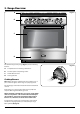
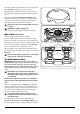
2. Range Overview DocNo.025-0101 - Overview - 90 DF SC - Prof+ FX A Fig.2-1 B C D PROFESSIONAL ArtNo.270-0029 - Prof+ 90SC annotated The dual fuel single cavity range (Fig.2-1) has the following features: A. 5 hotplate burners including a wok burner B. A control panel incorporating a timer C. A multi-function oven D. A storage drawer Fig.2-2 Cooktop Burners Note: Before using the cooktop make sure all burners are in place and all the grates on the range are properly placed.
The igniter should spark and light the gas. Keep holding the knob pressed in to let the gas through to the burner for about ten seconds. Fig.2-3 If, when you let go of the control knob, the burner goes out, then the FSD has not been bypassed. Turn the control knob to the OFF position and wait for one minute before you try again, this time making sure to hold in the control knob for slightly longer. Adjust the flame height to suit by turning the knob counterclockwise (Fig.2-3).
Position the griddle over the hotplate burners resting on the grates (Fig.2-9). Check that it is securely located. Fig.2-10 The griddle can be lightly brushed with cooking oil before use. Light the hotplate burners. Adjust the flame heights to suit. Preheat the griddle for a maximum of 5 minutes before adding food. Leaving it longer may cause damage. Turn the control knobs towards the low position, marked with the small flame symbol, to reduce the burner flames.
Function Thaw & serve To thaw small items in the oven without heat Convection oven A full cooking function, even heat throughout, great for baking Convection broiling Broiling meat and fish with the door closed Fan assisted Conventional oven Browning element The browning element and warming can be used in the latter part of the cooking process to fine-tune the results to your particular requirements.
Convection Oven This function operates the fans and the heating element around them (Fig.2-18). An even heat is produced throughout the oven, allowing you to cook large amounts quickly. Fig.2-16 A H B Convection oven cooking is particularly suitable for multirack cooking and is a good ‘all-round’ function. It may be necessary to reduce the temperature by approximately 20°F (10°C) for recipes previously cooked in a conventional oven.
Conventional Oven (Top and Base Heat) This function combines the heat from the top and base elements (Fig.2-21). It is particularly suitable for roasting and baking pastry, cakes and biscuits. Food cooked on the top rack will brown and crisp faster than on the lower rack, because the heat is greater at the top of the oven than at the base, as in ‘fan assisted oven’ function. Similar items being cooked will need to be changed around for even cooking (use racks 2 & 3).
Rotate the Adjusting knob to set the time required (Fig.2-26). Fig.2-26 You can either turn the knob back to the vertical manual setting [] to keep an eye on the time of day, or leave it in the [] minute minder position as the time ticks down. ArtNo.300-0006 2BC minute minder setting 2 Fig.2-27 ArtNo.301-0007 2BC Stopping the oven 1 To stop the beeper when it sounds, turn the Adjusting knob counter-clockwise. • • The ‘cook period’, which is the length of time you want the oven to cook for.
Fig.2-32 AUTO is Showing, But You Want to Revert to Manual Cooking Fig.2-33 Art No. 301-0011 2BC Activating the key lock 1 ArtNo.301-0012 2BC Activating the key lock 2 You can cancel any automatic settings by briefly turning the Timer knob to the clock symbol [] and then releasing it. Key Lock When the key lock is activated the left-hand oven is locked and will not come on. Fig.2-34 To Activate the Key Lock Make sure that the clock is in manual mode and cancel any active programs. Fig.2-35 ArtNo.
Shelves Fig.2-41 To Fit the Telescopic Shelf Runners Please note that it is not possible to fit telescopic runners to the bottom rack support location (Fig.2-41) With the runner arm in the closed position locate the opening of the upper rear slot onto the side support (Fig.2-42). Do not locate any further than the opening at this point. Although not shown in Fig.2-42, fitting is the same for the upper stud type supports.
Storage Fig.2-46 The bottom drawer is for storing oven trays and other cooking utensils. It can get very warm, so do not store anything in it that may melt or catch fire. Never store flammable materials in the drawer. This includes paper, plastic and cloth items, such as cookbooks, plastic ware and towels, as well as flammable liquids. Do not store explosives, such as aerosol cans, on or near the appliance. Flammable materials may explode and result in fire nn or property damage. Fig.
3. Cooking Tips Cooking with a Multi-function Oven General Oven Tips Remember: not all modes are suitable for all food types. The oven cooking times given are intended for a guide only. The wire racks should always be pushed firmly to the back of the oven. Tips on Cooking with the Timer Baking trays with food cooking on them should be placed level with the front edge of the oven’s wire racks. Other containers should be placed centrally.
4. Cooking Table DocNo.031-0004 - Cooking table - electric & fan single cavity The oven control settings and cooking times given in the table below are intended to be used AS A GUIDE ONLY. Individual tastes may require the temperature to be altered to provide a preferred result. 5 4 3 2 1 Food is cooked at lower temperature in a fan oven than in a conventional oven. When using recipes, reduce the fan oven temperature by 25°F (10 °C) and the cooking time by 5-10 minutes.
5. Troubleshooting Cooktop ignition or cooktop burners faulty If there is an installation problem and I don’t get my original installer to come back to fix it who pays? Is the power on? You do. Service organizations will charge for their service if they are correcting work carried out by your original installer. It is in your interest to track down your original installer.
The timed oven is not coming on when automatic cooking Fig.5-1 Has the oven knob been left in the OFF position by mistake? Is the oven locked (see above)? Oven temperature getting hotter as the range gets older ArtNo.324-0005 Oven light bulb If turning the knob down has not worked or only worked for a short time then you may need a new thermostat. This should be installed by a service technician. Fig.5-2 An oven light is not working The bulb has probably burnt out.
6. Cleaning Your Range Essential Information Before thorough cleaning, turn off the circuit breaker. Allow the range to cool. Fig.6-1 A After cleaning, remember to switch on the circuit breaker and reset the clock before re-using the range. ArtNo.311-0028 - Burner head off Never use paint solvents, caustic cleaners, biological nn powders, bleach, chlorine based bleach cleaners, B coarse abrasives or salt. Do not mix different cleaning products – they may nn react together with hazardous results.
Avoid using any abrasive cleaners including cream nn cleaners on brushed stainless steel surfaces. Fig.6-4 Never use caustic or abrasive cleaners as these will nn damage the surface. Griddle (Optional Extra) Always clean the griddle after use. Allow to cool completely before removing. Immerse the griddle plate in hot soapy water. Use a soft cloth or, for stubborn stains, a nylon washing up brush. ArtNo.272-0015 - 90DF - Pro+ - Removing the outer door panel Fig.
Refit in the reverse order, making sure to push the rack down onto the runner arms. Fig.6-7 To Remove and Refit the Ladder Rack Supports Lift the ladder support hooks out of the two locating holes in the oven side (or divider) before lifting the support clear of the bottom ladder restraint. Refit by inserting the bottom of the ladder into the restraint before fitting the hooks through the locating holes.
To Cancel the Self-cleaning Cycle To cancel the self-clean function, turn the Timer knob to the [] button and then rotate the adjusting knob counterclockwise to set the timer back to ( 0.00 ). The heating part of the cycle will end and the cooling part of the cycle will start. When the oven temperature has fallen sufficiently the interlock neon will go out and the door will unlock. ArtNo.301-0008 2BC Stopping the oven 2 Fig.6-12 When the door has unlocked turn the oven function control back to OFF. Fig.
WARNING! If the information in this manual is not followed exactly, a fire or explosion may result causing property damage, personal injury or death. Do not store or use gasoline or other flammable vapors and liquids in the vicinity of this or any other appliance. WHAT TO DO IF YOU SMELL GAS Do not try to light any appliance. Do not touch any electrical switch. Do not use any phone in your building. Immediately call your gas supplier from a neighbor’s phone. Follow the gas supplier’s instructions.
INSTALLATION Check the appliance is electrically safe and gas sound when you have finished. 7. Installation Regulations Important! Installation of this range must conform with local codes, or in the absence of local codes, with the National Fuel Gas Code, ANSI Z223.1/NFPA.54, latest edition. • • • In Canada, installation must conform with the current Natural Gas Installation Code, CAN/CGA-B149.1 or the current Propane Installation Code, CAN/CGA-B149.2, and with local codes where applicable.
INSTALLATION Check the appliance is electrically safe and gas sound when you have finished. Checking the parts: This will allow the range to be moved for cleaning or servicing. Also, make sure your floor covering will withstand 180 °F (80 °C); see the ‘Installation Safety Instructions’ section. 6 grates Allen key Make sure the wall coverings around your range can withstand the heat generated, up to 200 °F (90 °C), by the range; see the ‘Installation Safety Instructions’ section.
INSTALLATION Check the appliance is electrically safe and gas sound when you have finished. Positioning the Range Fig.7-1 Fig.7-1 shows the minimum recommended distances and clearances from the range to nearby surfaces. Min 35½” (90 cm) - 36“ (91 cm) For Canada, min 363/8” (92.5 cm) Min 31½” (80 cm) between the top of the cooktop and a horizontal combustible surface You MUST provide adequate clearances between the range and adjacent combustible surfaces.
INSTALLATION Check the appliance is electrically safe and gas sound when you have finished. Fitting the Oven Handle Fig.7-3 The handle is supplied as a handle assembly, 2 grub screws (supplied fitted to handle assembly) and an Allen key. Fit the assembled handle to the projecting mounting studs on the upper oven door and fix it in place by tightening the grub screws (Fig.7-3). ArtNo.063-0019 - 90 - SC - Aga Professional - Removing the door Moving the Range The range is very heavy. Take great care.
INSTALLATION Check the appliance is electrically safe and gas sound when you have finished. Lowering the Two Rear Rollers Fig.7-7 To adjust the height of the rear of the range, first fit a 13 mm spanner or socket wrench onto the hexagonal adjusting nut (Fig.7-7). Make 10 complete (360°) turns clockwise. Make sure you lower BOTH REAR ROLLERS. Note that the rollers are only intended to aid installation – the range should not be moved once it is installed. Completing the Move Fig.
INSTALLATION Check the appliance is electrically safe and gas sound when you have finished. Adjust and lock the inner anti-tip bracket to give a 1/8” (3 mm) clearance above the engagement edge in the back of the range (Fig.7-11). Fig.7-11 Stabilitybracket bracket Anti-tip Wall Fixing Cooker Range Where floor fixing is impractical and provided that the outer anti-tip bracket can be attached to a solid wall, the anti-tip device may be attached to a wall (Fig.7-12).
INSTALLATION Check the appliance is electrically safe and gas sound when you have finished. Electrical Connection Fig.7-15 When installed the range must be electrically grounded in accordance with local codes or; in the absence of local codes with the National Electrical Code ANSI/NFPA 70, latest edition. 16” (41 cm) ArtNo.281-0013 - Albertine SC - Electrical location In Canada the range must be installed in accordance with the current CSA Standard C22.1 – Canadian Electrical Code Part 1.
INSTALLATION Check the appliance is electrically safe and gas sound when you have finished. Connecting if the Supplied Cord and Plug is Not Suitable Fig.7-17 To access the electrical connections, undo the screws and remove the electrical cover (Fig.7-16). 4-Wire Conduit Installation Disconnect the supplied power cord from the terminal block and ground post. Keep the terminal block parts; you will need them.
INSTALLATION Check the appliance is electrically safe and gas sound when you have finished. Attach the ground strap to the ground and center terminal of the connector block. Fig.7-23 The neutral or ground wire of the power cord must be connected to the neutral terminal located in the center of the connector block. The power leads must be connected to the outside terminals. ArtNo.280-0039 Reducer Plate Make sure the connections are tight. Now tighten the strain relief device to clamp the power cord.
INSTALLATION Check the appliance is electrically safe and gas sound when you have finished. Gas Connection Fig.7-26 Installation of this range MUST conform with local codes or, in the absence of local codes, with the National Fuel Gas Code, ANSI Z223.1-latest edition. 16” (41 cm) In Canada The range MUST be installed in accordance with the current CGA Standard CAN/CGA-B149 – Installation Codes for Gas Burning Appliances and Equipment and/or local codes. 2.5” (6.5 cm)- Wall behind the range ArtNo.
INSTALLATION Check the appliance is electrically safe and gas sound when you have finished. Connect the Range to the Gas Supply Fig.7-29 Shut off the main gas supply valve before disconnecting the old range and leave it off until the new hookup has been completed. Do not forget to relight the pilot on other gas appliances when you turn the gas back on.
INSTALLATION Check the appliance is electrically safe and gas sound when you have finished. Seal the Openings Fig.7-30 Seal any openings in the wall behind the range and in the floor under the range when hookups are completed. IMPORTANT: When all connections are completed make sure the flow of combustion and ventilation air to the range is unobstructed.
INSTALLATION Check the appliance is electrically safe and gas sound when you have finished. Range Operational Checks Refitting the Range Oven Check Reverse the above procedure to refit. If the gas line has been disconnected, check for gas leaks after reconnection. Turn on the oven and check that the oven fans start to turn and that the oven starts to heat up. Turn off the oven. Note: A suitably qualified person should disconnect and reconnect the gas supply.
CONVERSION Check the appliance is electrically safe and gas sound when you have finished. 8. Conversion to Another Gas Important! Fig.8-1 • • • Observe all governing codes and ordinances. The range must be properly grounded. Save these instructions for the local electrical inspector’s use. When servicing or replacing gas carrying components disconnect from the gas supply before commencing operation and check the appliance is gas sound after completion.
CONVERSION Check the appliance is electrically safe and gas sound when you have finished. Remove the electrical connections from the rear. Taking care not to damage the control panel, and protecting it with cloth for example, rest it on the open oven door. ArtNo.0102-0011 - Screwing the control valve bypass screw Fig.8-3 Turn the bypass screw on each control clockwise to the stop (Fig.8-3). Connect the electrical connectors to the rear of the control panel and locate it over the front lip of the hob.
CONVERSION Check the appliance is electrically safe and gas sound when you have finished. Type 2 Fig.8-8 The regulator has a bayonet mounted top cap (Fig.8-8). Using a small coin, press in and turn the cap to remove it. Turn the cap over so that the letters “LP” are visible on base of the hollow in the cap (Fig.8-9). Refit the cap, making sure that the bayonet pins are securely located. ArtNo.
CONVERSION Check the appliance is electrically safe and gas sound when you have finished. Refitting the Grille and Drawer Fig.8-12 Refitting the Flue Grille Locate the grille onto the flue and secure to the cooktop with the 5 screws supplied (Fig.8-12). Refitting the Storage Drawer Slide the inner side rails out until fully extended (Fig.8-13). Lift the drawer at its sides and locate one of the drawer rails (approximately ½ (15 mm)) onto an inner side rail (Fig.8-14).
9.
10. Technical Data INSTALLER: Please leave these instructions with the user. RATING PLATE LOCATION: Inside base drawer of cavity. Remove the drawer (see ‘Overview’ > ‘Storage’ for details). COUNTRY OF DESTINATION: USA, Canada Connections Electric 240 V 60 Hz Gas ArtNo280-0090 Drawer Cavity & Badges ½” NPT at rear left-hand side Dimensions Overall height minimum 373/8” (95 cm) maximum 383/8” (97.5 cm) Overall width 357/16” (90 cm); see ‘Positioning of Range’.
43
44
CONSUMER WARRANTY ENTIRE PRODUCT – LIMITED ONE YEAR WARRANTY AGA warrants the replacement or repair of all parts, including gas components of this range cooker which prove to be defective in material or workmanship, with the exception of the painted or porcelain enamel finish or plated surfaces, for one year from the date of original purchase. Such parts will be repaired or replaced at the option of AGA without charge, subject to the terms and conditions set out below.
AGA Marvel 1260 E. VanDeinse St. Greenville, MI 48838 Business (616) 754-5601 Fax (616) 754-9690 Toll Free Telephone 800-223-3900 www.aga-ranges.