
Installation Guide

15
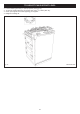
CONNECTING TO GAS
CAUTION: ENSURE THAT THE RANGE IS ISOLATED FROM ELECTRIC SUPPLY.
The range can be installed with an approved flexible connection. Supply piping should not be less than
3
/8” I/D flexiline.
Connection is made to the
1
/2” NPT female thread located on the rear right hand side of the range.
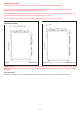
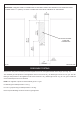
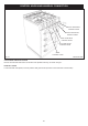
The gas flexiline connector provided, must be fitted to the wall in the shaded area dimensioned in Fig. 14. Take into account
that it must be possible to pull the cooker forward sufficiently for servicing. Ensure hose is not trapped between range back
panel and rear wall. Ensure hose is routed away from the vent slots in the back panel. The hose must be in accordance
with the relevant standards.
IMPORTANT THE GAS SUPPLY CONNECTION AT THE WALL MUST NOT PROJECT OUT FROM THE WALL BY
MORE THAN 1
3
/4” (45mm) SO THAT IT DOES NOT FOUL WITH THE BACK OF THE RANGE .
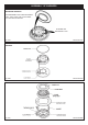
FLEXIBLE HOSE
Use the proper gas connector flexible hose approved for residential use.
NOTE: Use soapy water solution on new gas connections to ensure there are no gas leaks.
NOTE: AN EASILY ACCESSIBLE GAS SHUT OFF VALVE MUST BE FITTED BEFORE THE METAL FLEX GAS LINE.
Check for gas soundness after connecting the appliance.
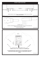
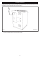
Fig. 12 DESN 517234
REGULATOR GAS
INLET
1
/2” NPT
PRESSURE
TEST POINT