AGA TOTAL CONTROL Model No. - TC3 & TC5 Installation Guide REMEMBER: when replacing a part on this appliance, use only replacement parts that you can be assured conform to the safety and performance specification that we require. Do not use reconditioned or copy parts that have not been clearly authorised by AGA. PLEASE READ THESE INSTRUCTIONS BEFORE COMMENCING SITE SURVEY OR INSTALLING THIS APPLIANCE.
CONTENTS SECTION PAGE GENERAL NOTES 3 DELIVERY REQUIREMENTS 3 GENERAL INSTALLATION REQUIREMENTS 3 APPLIANCE DIMENSIONS - AGA TC3 4 APPLIANCE DIMENSIONS - AGA TC5 5 INSTALLATION 6 CONNECTING TO THE POWER SUPPLY - AGA TC3 8 POWER SUPPLY - HOTCUPBOARD (AGA TC5) 9 MAINS SUPPLY LOCATION - AGA TC3 10 MAINS SUPPLY LOCATION - AGA TC5 11 HOTCUPBOARD INSTALLATION 12 HANDRAIL CONNECTION - AGA TC3 17 MAINS CORD AND WIRING DIAGRAM - AGA TC3 18 WIRING DIAGRAM - AGA TC5 (HOTCUPBOARD) 19 INST
GENERAL NOTES NOTE: THESE INSTALLATION INSTRUCTIONS SHOULD BE LEFT WITH THE APPLIANCE AND THE USER TO RETAIN FOR FUTURE REFERENCE. Before installation of an AGA can be made, the site is inspected for suitability by an authorized AGA distributor and corrected where necessary to conform with local or regional electrical codes. USA Model Number AGA TC3 FCC ID: A2M-AGA-TC3 FCC ID: A2M-AGA-TC3CKR CANADA Model Number AGA TC3 IC: 10181A-AGATC3CKR This device complies with part 15 of the FCC Rules.
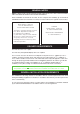
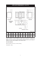
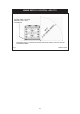
APPLIANCE DIMENSIONS - AGA TC3 RH SIDE VIEW FRONT VIEW LH SIDE VIEW PLAN VIEW MINIMUM WALL POSITION MINIMUM WALL POSITION Fig. 1 DESN 516297 A B C D E F G H J K mm 987 945 910 680 1385 760 1145 698 116 10 ins 38 7/8 37 3/16 35 13/16 26 3/4 54 1/2 29 15/16 45 1/16 27 1/2 4 9/16 3/8 Cooker Dimensions When surveying for a cooker installation the actual clearance required for the ‘body’ of the appliance should be increased by 3/8” (10mm) beyond the figures quoted above.
APPLIANCE DIMENSIONS - AGA TC5 Fig. 2 mm ins DESN 516561 A B C D E F G H J K L 1478 945 910 680 1385 760 1145 698 116 10 634 26 3/4 54 1/2 29 15/16 45 1/16 27 1/2 4 9/16 3/8 24 31/32 58 13/16 37 3/16 35 13/16 Cooker Dimensions When surveying for a cooker installation the actual clearance required for the ‘body’ of the appliance should be increased by 10mm beyond the figures quote above.
INSTALLATION Range Base or Hearth It is essential that the base or hearth on which the range stands should be level and be capable of supporting the total weight of the range. The base of the built-in AGA plinth must be level and sit above finished floor height for service access. Plinth The front plinth cover is removable and must not be obstructed by flooring or tiles. If necessary the cooker must be raised by the thickness of the tiles to ensure the plinth can be removed.
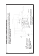
Fig. 3 DESN 516589 7 CABINETS MUST NOT EXCEED 13” PROJECTED DEPTH ABOVE THE RANGE. DIM ‘D’ TO BE NOT LESS THAN THE NORMAL WIDTH OF THE APPLIANCE.
CONNECTION TO THE POWER SUPPLY - AGA TC3 Electric Shock Hazard Rating Plate is located behind removable plinth, see Fig. 4. Electrical Grounding is required on this appliance. DO NOT connect to the electrical supply until the appliance is permanently grounded. Disconnect the power to the junction box before making the electrical connection.
POWER SUPPLY - HOTCUPBOARD (AGA TC5) The hotcupboard attachment requires an independent single phase supply. It has a maximum load of 6 amps, protected by an appropriate branch circuit supply. 110/120V 60 Hz FLEXIBLE CORD AND PLUG PARALLEL TYPE. The appliance when installed, must be electrically grounded in accordance with local or regional codes. An electrical socket must be provided within 5 feet of the LH side of the appliance and easily accessible to the user to disconnect.
MAINS SUPPLY LOCATION - AGA TC3 RATING LABEL LOCATED BEHIND PLINTH, PULL TO REMOVE THE MAINS SUPPLY CONNECTION AND ISOLATION POINT MUST BE WITHIN THE ZONE SHOWN Fig.
MAINS SUPPLY LOCATION - AGA TC5 HOTCUPBOARD POWER SUPPLY MAINS CABLE FED FROM CONTROL TRAY LEFT OR RIGHT EXIT THROUGH DUCTING DEPENDENT UPON POSITION OF SUPPLY SOCKET Fig. 5 DESN 516562 RATING LABEL LOCATED BEHIND PLINTH, PULL TO REMOVE, THE MAINS SUPPLY CONNECT POINT MUST BE WITHIN THE ZONES SHOWN Fig.
HOTCUPBOARD INSTALLATION NOTE: The AGA TC5 hotcupboard should arrive with the top plate in a jacked up position. This is to allow the complete appliance to be slid onto its plinth when alongside the AGA TC3 without the top plate clashing. The hotcupboard top plate should then be wound down to its correct height once the appliance is in its final position. 1. Detach hotcupboard from the plinth by removing two screws and tongue bracket from plinth (See Fig. 6).
2. Position the plinth alongside the AGA Total Control leaving no gap between the two plinths (See Fig. 8). Check with a spirit level that the plinth level is correct, and also check height differential between the hotcupboard plinth and Total Control plinth is correct 7/16” (11mm). If necessary, use shims in each corner to level the plinth. HOTCUPBOARD PLINTH BASE 7/16” +1 (11mm) - 0 HEIGHT DIFFERENTIAL Fig. 8 DESN 516564 3.
4. Run a straight edge along the front of the AGA Total Control plinth, to ensure the front face of both plinths sit squarely against the straight edge. (See Fig. 10) When satisfied both plinths sit squarely, jacking screws can be tightened until they just make contact with the AGA Total Control plinth and locking screws can now be tightened. USE STRAIGHT EDGE ACROSS BOTH PLINTHS TO ENSURE PLINTHS ARE ALIGNED SQUARELY Fig. 10 DESN 516551 5.
6. Slide hotcupboard onto plinth until rear tongue bracket engages fully into rear of base slot, (See Fig. 12). Ensure the appliance is aligned squarely with the plinth then proceed to engage the front tongue bracket into the slot on the underside of the base plate. Once satisfied that the front tongue bracket is engaged fully lock it into place by tightening the two M6 screws fully. Fig. 12 DESN 516552 7. The hotcupboard top plate is set 13/64 (5mm) higher than the AGA Total Control top plate.
8. Using the stay rod nut adjusting tool, carefully lower the top plate adjusting nuts until the top plate sits at the required height, making sure that the top sits level and matches the height of the AGA TC3. (See Fig. 14). For servicing requirement, top plate should be removed by raising adjusters approximately 5mm, the top plate can now be removed easily without causing damage to the enamelled surfaces.
Fig. 15 DESN 516569 HANDRAIL CONNECTION - AGA TC3 Fig. 16 DESN 516560 Handrail brackets. endcaps and handrails require assembly. Locate endcaps onto handrail, place brackets over endcaps and then slide complete assembly onto locating studs. Once assembly is correctly located, lock into position with grub screws (located on underside of handrail).
MAINS CORD AND WIRING DIAGRAM - AGA TC3 Fig.
WIRING DIAGRAM - AGA TC5 (HOTCUPBOARD OPTION) COLOUR KEYS/COLLEURS CAUTION: LABEL ALL WIRES PRIOR TO DISCONNECTION, WHEN SERVICING CONTROLS WIRING ERRORS CAN CAUSE IMPROPER AND DANGEROUS OPERATION. VERIFY PROPER OPERATION AFTER SERVICING ATTENTION: ETIQUETEZ TOUS LES CABLES AVANT DE LES DEBRANCHER LORS DE LES BRANCHER LORS DE L’ENTRETIEN DES COMMANDES. DES ERREURS DE CABLAGE PEUVENT ENTRAINER UN FONCTIONNEMENT INCORRECT ET DANGEREUX. VERIFIEZ QUE L’ APPAREIL FONCTIONNE CORRECTEMENT APRES L’ENTRETIEN. Fig.
INSTRUCTIONS Attach warning hanger (EGLL516660) located in literature pack, to AGA Total Control handrail when installation is complete. Advise customer to remove and read warning label. Hand this Installation Guide to the user for retention and instruct in the safe operation of the appliance. Also advise the user that, for continued efficient and safe operation of the appliance, servicing is carried out at intervals recommended by the AGA distributor.
For further advice or information contact your local AGA Specialist With AGA’s policy of continuous product improvement, the Company reserves the right to change specifications and make modifications to the appliance described and illustrated at any time US Office: AGA MARVEL 1260 E Van Deinse St. Greenville, MI 48838 www.agamarvel.