
Specification

3
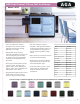
AGA Total Control 3-Oven Cast Iron Range
Model # ATC3
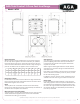
Range Dimensions
When surveying for range installation the actual clearance required
for the ‘body’ of the appliance should be increased by ⅜" (1000mm)
beyond the gures quote above. This allows safe margin to take into
account the natural dimensional variations found in major castings. In
particular the width across the appliance recess could be critical.
Range Base or Hearth
It is essential that the base or hearth on which the range stands should
be level. The base of the built-in AGA plinth must be level and sit above
nished oor height for service access.
Plinth
The front plinth cover is removable and must not be obstructed by
ooring or tiles. If necessary the range must be raised by the thickness of
the tiles to ensure the plinth can be removed.
Minimum Clearance to Combustibles
A gap of at least ½" must be observed between the rear of the top plate,
and the wall behind the appliance. If the rear wall is of combustible
material there must be a gap of 1" (25mm).
Side Clearances
A ⅛" (3mm) gap is required each side between the range top
plate and adjoining work surfaces that may be tted, this is
to allow for the safe removal of the top plate should this be
required at a later date.
Where ranges are tted against side walls a 49/16" (116mm)
side clearance is required on the right and left hand side for
oven doors access.
If the AGA is to be installed in a brick recess, then the minimum
clearance should be increased by at least ⅜" (10mm), to allow
for the walls not being square.
In addition a minimum clearance of 39½" (1000mm) must be
available at the front of the range to enable it to be serviced.
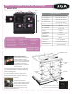
Range Hoods
It is recommended this AGA is tted with a range hood. The
AGA venting system is located on top of the AGA between the
two hotplates, and is designed for venting the moisture from
the ovens. The range hood should be positioned not less than
the minimum height as recommended by the manufacturer,
from the top of the AGA.
A B C D E F G H J K
mm 987 945 910 680 1385 760 1145 698 116 10
ins 38
⅞
37
/
35
/
26
¾
54 ½ 29
¹
/
45
/
27
½
4
9/
/8
Installation
Specications are subject to change without notice. Visit www.aga-ranges.com for the most up-to-date information.