AGA TOTAL CONTROL TC3 User Guide & Installation Instructions REMEMBER, when replacing a part on this appliance, use only spare parts that you can be assured conform to the safety and performance specification that we require. DO NOT use reconditioned or copy parts that have not been clearly authorised by AGA. PLEASE READ THESE INSTRUCTIONS BEFORE USING THIS APPLIANCE AND KEEP IN A SAFE PLACE FOR FUTURE REFERENCE.
Make a note of your AGA Total Control Serial Number when it is being installed. The serial number can be found behind the magnetic plinth cover.
Contents 1. Product Safety 1 10. Installation Instructions 27 2. Health & Safety 3 11. Installation Introduction 28 3. Introduction 5 12. Location 29 4. Overview 6 13. Connection to the Power Supply 32 5. Operating the AGA Total Control 7 6. 7. 8. 9. Getting started 8 General Advice 9 Handset Fig. 5.
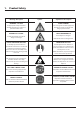
1. Product Safety Meaning / Description Symbol Signification / Description WARNING / CAUTION AVERTISSEMENT An appropriate safety instruction should be followed or caution to a potential hazard exists. Une consigne de sécurité appropriée doivent être suivies ou garde d’un danger potentiel exists. DANGEROUS VOLTAGE TENSION DANGEREUSE To indicate hazards arising from dangerous voltages. Pour indiquer les dangers résultant des tensions dangereuses.
Important Safety Instructions INCORRECT USE OF THIS RANGE CAN INCREASE THE RISK OF FIRE, ELECTRIC SHOCKS OR INJURY TO PERSONS. PLEASE READ THE FOLLOWING PRECAUTIONS TO REDUCE THESE RISKS. This appliance is not intended for use by persons (including children) with reduced physical, sensory or mental capabilities, or lack of experience and knowledge, unless they have been given supervision or instruction concerning use of the appliance by a person responsible for their safety.
2. Health & Safety Consumer Protection • Always when opening an oven door, allow hot air and steam to escape. As a responsible manufacturer, we take care to make sure that our products are designed and constructed to meet the required safety standards when properly installed and used. • Always use dry pot holders. Moist pot holder will cause steam burns. Do not use towels or other cloths near the heated plates.
• Never install cabinets (shelves) or similar above the range with a depth greater than 13” (330mm). Do not hang dish towels on the left hand side of the AGA handrail. Doing so will block the air vent. Blocking the air vent can cause excessive temperature increase to the control panel and prevents easy access to the controls. • Never heat unopened food containers. Pressure buildup may cause the container to burst and cause injury. • Never reach directly into a hot oven to add or remove cooking utensils.
3. Introduction As responsible manufacturers we take care to make sure that our products are designed and constructed to meet the required safety standards when properly installed and used. Your new AGA Total Control gives you everything you love about the classic AGA heat storage cooker, but with the added convenience of touchscreen technology and the ability to turn each cooking area on and off, as and when you want it.
4. Overview WARNING: ACCESSIBLE PARTS MAY BECOME HOT DURING USE. TO AVOID BURNS AND SCALDS CHILDREN SHOULD BE KEPT AWAY. AGA TC3 Fig. 4.1 Boiling Plate Simmering Plate Top Plate Control Panel Roasting Oven Baking Oven Slow Cook Oven DESN 517448 The AGA TC3 has the traditional cast iron ovens with independently controlled hotplates. Baking Oven A moderate oven for cooking cakes and biscuits, baking fish, lasagne or shepherds pie, plus roasting meat and poultry at a medium heat.
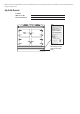
5. Operating the AGA Total Control Fig. 5.1 DESN 517464 Control Panel Fig. 5.1 Fig. 5.2 This is situated behind the top left hand door. The control panel contains touch sensitive buttons with a green or orange light (LED indicator) to indicate which zone is activated. An audible beep will confirm selection. Handset Fig. 5.2 Your AGA Total Control cooker also comes with a Handset which can be used to program the ovens. It displays the time, date and program events. The hotplates work on Manual only.
Getting started The appliance has 4 operating modes: When switching on the AGA cooker for the first few times, there are two things you may notice, neither of which should cause concern. Mode Selection Button 1. Standby Button 2. Manual > Slumber > AUTO > AUTO/Slumber selection can only be made when standby button is on. A little smoke and some odour may be emitted when first switched on.
General Advice PLEASE NOTE: • Don’t forget to include time for warm-up. Food SHOULD NOT be placed into any oven until it is up to normal operating heat i.e. the green light of the selected oven is solid and not flashing. • Don’t forget if you have set the AUTO program and have selected the AUTO mode, an oven or ovens must be selected. The oven doors should not be left open for long periods of time during cooking and heating up. • The hotplates can only be operated manually.
Handset Fig. 5.2 Communication or ‘Handshake’ button Used initially to synchronise the handset to the AGA Total Control. (On day of installation or in case of replacement handset.) The handset displays the time, date and events. Programming is via eight push buttons. The information is displayed via a back-lit LCD screen. Clock button Opens and closes the date and time settings screen. Screens Left/Back button Moves back and highlights the previous setting. The handset has 3 main screens.
Handset Failure Fig. 5.3 In the unlikely event of handset failure, the appliance would still be operational with the last selected program. The cooker can also be changed to Manual mode from one of the auto modes using the mode button on the control panel. If the handset is damaged or lost, a replacement can be obtained from AGA and re-programmed to suit your appliance. DO NOT PLACE THE HANDSET ON ANY HOT nn SURFACES.
Date and Time Setting Fig. 5.6 Press and hold Clock button until the screen is displayed Fig. 5.6. In this screen the time, date, month and year can be altered/set. button at any stage to save the settings and exit the Press DATE/TIME screen. Press the and buttons to alter the highlighted time, date, month and year settings. ‘Message sent OK’ will appear on the screen when the handset is in range of the cooker. Press the and buttons to cycle between the time, date, month and year.
How you do it 1. Fig. 5.8 Press the or buttons to navigate through the settings on the screen. When a setting is selected it will be highlighted by a dark box. Pressing the and buttons. will change the information in this highlighted box. 2. Press 3. If you have made changes and wish to exit this screen, press the button. A ‘Save Changes’ - Yes or No? message will appear on the screen. 4. Pressing the and buttons will highlight Yes or No. Press the button again to confirm your choice. A. B. D.
Power Outages under 10 minutes Fig. 5.9 When the power is restored, the AGA Total Control will resume normal operation as was set prior to the power interruption. Power Outages over 10 minutes Most functions will have turned OFF. • ‘Manual’ mode - all zones OFF. • ‘Slumber’ mode - hotplates OFF, Slumber ON • ‘AUTO’ mode - hotplates OFF, ovens continue with the set programme. DESN 517480 Fig. 5.10 • ‘AUTO/Slumber’ - hotplates OFF, ovens continue with the set programme.
6. AGA Accessories To get the very best performance from your range we recommend AGA saucepans with the thick tri-core bases and stacking lids so that the maximum use of oven space is made and an AGA kettle for boiling water. AGA Accessories can be viewed at your AGA Specialist or online at www.agacookshop. co.uk Fig. 6.1 Getting to know your AGA If you have not already seen a demonstration, ask your AGA Specialist for details.
1 Cold Plain Shelf (Fig. 6.5) Fig. 6.5 This has two uses one as large baking sheet for scones, biscuits, pastry items and meringues and the other use as a heat deflector to cut off the top heat if food is overbrowning before it is cooked through. DO NOT STORE IN THE OVENS WHEN NOT IN USE. nn Roasting Oven Perforated Baffle (Fig. 6.6) A roasting oven perforated baffle is positioned in the top of the roasting oven, in order to optimise cooking performance.
Fitting the Oven Shelves Fig. 6.1 Fig. 6.2 DESN 512403 DESN 512404 Removing the Oven Shelves Fig. 6.3 Fig. 6.
7. The Ovens Your AGA Total Control has three ovens, each of which is preset at a different heat, just like the classic AGA heat storage cooker. They are named as: • The Roasting Oven for high temperature cooking • The Baking Oven for moderate temperature cooking • The Slow Cook Oven for long slow low temperature cooking DO NOT OPERATE THIS APPLIANCE WITH THE DOORS nn OPEN, SINCE THIS CAN CAUSE A LOCK-OUT.
Fig. 7.1 Boiling Plate Simmering Plate Top Plate Control Panel Roasting Oven Baking Oven Slow Cook Oven DESN 517448 The Roasting Oven Fig. 7.2 The roasting oven is indirectly heated by two elements, one in the base of the oven and the other in the roof. These elements heat the air and the cast iron within to provide cooking results consistent with the classic AGA heat-storage cooker, with the flexibility of being able to turn it to Slumber or Off when not required.
The Baking Oven The roasting oven can used for ‘grilling’ at the top and ‘shallow frying’ on the oven floor. The baking oven is indirectly heated by two elements, one in the base of the oven and the other in the roof. These elements heat the air and the cast iron within to provide cooking results consistent with classic AGA heat-storage cookers, with the flexibility of being able to turn it to Slumber or Off when not required.
Slow Cook Oven Fig. 7.3 The slow cook oven is indirectly heated by one element in the base of the oven. This element heats the air and the cast iron within to provide cooking results consistent with the traditional slow cook oven of the classic AGA heat-storage cooker, with the flexibility of being able to turn it to Off when not required. The slow cook oven is always at a simmer or Slumber mode ideal for long slow cooking.
Using the zones of the AGA Total Control The whole hotplate area can be used for cooking and several pans can be accomodated on a single plate at any one time. The hotplates are set very slightly above the top plate to avoid accidental scratching if the pans are pulled to one side. DO NOT drag the utensils from one plate to another as the enamel will suffer! The different zones of the AGA Total Control cooker are described in the following pages individually.
CAUTION: This unit is heavy, proper equipment and adequate manpower must be used to remove the oven doors. Fitting the Doors Fig. 7.1 Fig. 7.2 DESN 517491 DESN 517489 Removing the Doors Fig. 7.3 Fig. 7.
8. Cleaning & Caring for your Range WARNING: ACCESSIBLE PARTS MAY BECOME HOT DURING USE. TO AVOID BURNS AND SCALDS CHILDREN SHOULD BE KEPT AWAY. Cast iron ovens and hotplates REMEMBER: be careful of the hot appliance. nn For most cleaning it is best when the appliance is nn turned off. Ovens - are made from cast iron and keep themselves clean. They are very durable, but will rust if surface moisture is left on them. Remember to always switch the ovens on, to dry them out after cleaning.
WARNING: ACCESSIBLE PARTS MAY BECOME HOT DURING USE. TO AVOID BURNS AND SCALDS CHILDREN SHOULD BE KEPT AWAY. Roasting Pans The enamelled roasting pans supplied with the AGA Total Control should be cleaned in hot soapy water, soaking if necessary. A nylon scouring pad can also be used. They may also be cleaned in the dishwasher, but with constant use, the enamelled finish will become dull in appearance. DO NOT use caustic cleaners or oven cleaners.
9. Troubleshooting ERROR CODES In the unlikely event an error occurs with your AGA Total Control cooker, error codes may be displayed on your handset, for example: 133 nn Please provide AGA Service with this information. It will assist the service engineer with diagnosing your fault.
10. Installation Instructions CAUTION: THIS UNIT IS HEAVY, PROPER EQUIPMENT AND ADEQUATE MANPOWER MUST BE USED IN MOVING THE RANGE TO AVOID DAMAGE TO THE UNIT OR THE FLOOR. REMEMBER, when replacing a part on this appliance, use only spare parts that you can be assured conform to the safety and performance specification that we require. DO NOT use reconditioned or copy parts that have not been clearly authorised by AGA.
11. Installation Introduction Health and Safety In your own interest and that of safety to comply with the law, all appliances should be installed by an authorized AGA distributor in accordance with the relevant regulations. Consumer Protection As responsible manufacturers we take care to make sure that our products are designed and constructed to meet the required safety standards when properly installed and used.
12. Location Refer to Fig. 12.1 to Fig. 12.3. It is recommended that any soft material flooring is removed from where the AGA will be installed. It is essential that the base or hearth on which both range and/or module stands should be level and capable of supporting the total weight of one or both units. The front plinth cover is removable and must not be obstructed by flooring or tiles. If necessary the range must be raised by the thickness of the tiles to ensure the plinth can be removed.
Specifications Fig. 12.
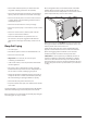
Fig. 12.2 Fitting the Handrail 1. Fit the handrail bracket over the fixing stud located on the top plate. Lock into position by tightening the grub screw nearest the appliance Fig. 12.2. 2. Slide the handrail through the handrail brackets Fig. 12.3. 3. Once the handrail assembly is located squarely, lock the handrail in position by winding in the grub screws on the underside of each handrail bracket. 4. Once the handrails are locked in position, fit the handrail endcaps.
13. Connection to the Power Supply Electric Shock Hazard The rating plate is located behind the removable plinth, see Fig. 13.2. If the supply cord is damaged, it must be replaced by the manufacturer, its service agent or similarly qualified person to avoid a hazard. Electrical Grounding is required on this appliance. DO NOT connect to the electrical supply until the appliance is permanently grounded. This appliance must be connected to a grounded, metallic, permanent supply.
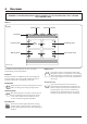
Mains Supply Location Fig. 13.1 Mains cable fed from control tray right-hand exit through ducting dependent upon position of supply socket DESN 517444 Fig. 13.2 Data plate located behind toe-kick, pull toe-kick to remove.
DESN 517484 14.
15. Warranty Welcome What is not included in the guarantee • Consumable parts Thank you for choosing an AGA cooker. We are sure that you will be impressed with the performance of your new AGA appliance and with the ongoing service you will receive. • Flues (except integral power and balanced flues). • Any labor charges not directly connected with the repair or replacement of a faulty component.
Regular Servicing Flues, Ventilation and External Services: Regular maintenance is an essential part of keeping your AGA range running safely and efficiently. External services, gas supply, external oil lines, tanks and filters are not covered under this warranty. Since your AGA can operate continuously it is important to ensure regular servicing is undertaken by AGA Service or your Authorized AGA Distributor. Only genuine AGA spare parts are used.
16. Service • In the event of your range requiring maintenance, please contact AGA Marvel or your AGA Retailer. • Your range must only be serviced by a qualified engineer, from an authorized AGA Specialist. • Do not alter or modify the range. • Only the parts specified by the manufacturer, are to be fitted. • The appliance warranty does not cover Commercial use.
38
For further advice or information contact your local AGA Specialist With AGA Marvel’s policy of continuous product improvement, the Company reserves the right to change specifications and make modifications to the appliance described and illustrated at any time. Supplied by AGA Marvel 1260 E. Van Deinse St. Greenville, MI 48838 Business (616) 754-5601 Fax (616) 754-9690 Toll Free Telephone 800-223-3900 www.agamarvel.