ELECTRIC MODULE (FFD) (with Gas Hob) Installation Instructions REMEMBER: when replacing a part on this appliance, use only spare parts that you can be assured conform to the safety and performance specification that we require. Do not use reconditioned or copy parts that have not been clearly authorised by AGA.
CONTENTS SECTION PAGE INTRODUCTION 3 TECHNICAL DATA 4 ELECTRICAL CONNECTION 5 LOCATION 6 SPECIFICATION - AGA GC (2 OVEN) WITH MODULE 7 SPECIFICATION - 3 OVEN AGA WITH MODULE (GC3M) 8 SPECIFICATION - AGA GC3 (POWER FLUE) WITH MODULE 9 INSTALLATION SEQUENCE AND PROCEDURE 10 - 16 SERVICING 17 WIRING DIAGRAM 18 2
INTRODUCTION WARNING: THIS APPLIANCE SHALL BE INSTALLED IN ACCORDANCE WITH THE REGULATIONS IN FORCE AND ONLY USED IN A WELL VENTILATED SPACE. READ THE INSTRUCTIONS BEFORE INSTALLING OR USING THIS APPLIANCE. PRIOR TO INSTALLATION, ENSURE THAT THE LOCAL DISTRIBUTION CONDITIONS (NATURE OF THE GAS AND GAS PRESSURE) AND THE ADJUSTMENT OF THE APPLIANCE ARE COMPATIBLE. THE ADJUSTMENT CONDITIONS FOR THIS APPLIANCE ARE STATED ON THE DATA PLATE.
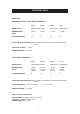
TECHNICAL DATA HOTPLATE NATURAL GAS G20 - (APPLIANCE CATEGORY I2H) R.H.F. L.H.R. R.H.R. L.H.F. BURNER TYPE ULTRA-RAPID RAPID SEMI-RAPID SEMI-RAPID MAXIMUM HEAT INPUT 3.5 kW 3.0 kW 1.75 kW 1.75 kW INJECTOR MARKING 130 116 097 097 PRESSURE POINT POSITION: REAR LH SIDE OF APPLIANCE JUST BELOW HOTPLATE LEVEL PRESSURE SETTING: 20mbar BURNER IGNITION: H.T. SPARK (APPLIANCE CATEGORY I3+) R.H.F. L.H.R. R.H.R. L.H.F.
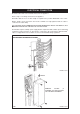
ELECTRICAL CONNECTION Electrical connections are located at the back of the appliance. Refer to Figs. 1 for wiring connection to the appliance. Remember that an excess of cable length is required for the possible withdrawal of the cooker. Always double check connections and ensure terminals are fully tightened and the cable is secured to the cable clamp. THE ISOLATOR SHOULD NOT BE POSITIONED IMMEDIATELY ABOVE THE MODULE, BUT MUST BE SITED WITHIN 2 METRES OF THE APPLIANCE.
LOCATION This is a class 2, type X appliance. The side wall above the hob shall be greater than 60mm from the cooker, only when adjacent to combustible material. Surfaces over the top of the cooker must not be closer than 650mm. The vent slots in the back of the top plate (or shroud) must not be obstructed. If possible, any hot water pipes from the AGA Cooker should be routed away from the Module.
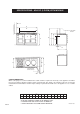
SPECIFICATIONS - AGA GC (2 OVEN) WITH MODULE E A N POSITION OF LIDS WHEN RAISED G C F B O L D M H J OVEN DOOR IN OPEN POSITION K COOKER DIMENSIONS When surveying for a cooker installation the actual clearance required for the ‘body’ of the appliance should be increased overall by 10mm beyond the figures quoted below. This allows safe margin to take into account the natural dimensional variations found in major castings. In particular the width across an appliance recess could be critical.
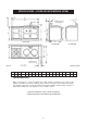
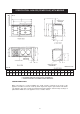
SPECIFICATIONS - 3 OVEN AGA WITH MODULE (GC3M) FIG. 2A DESN 512430 A B C D E F G H J K L M N mm 1598 889 851 679 467 1035 41 1330 756 1125 73 39 3 P S T 698 1533 800 U W 60 116 COOKER DIMENSIONS When surveying for a cooker installation the actual clearance required for the ‘body’ of the appliance should be increased overall by 10mm beyond the figures quoted below. This allows safe margin to take into account the natural dimensional variations found in major castings.
SPECIFICATION - AGA GC3 (POWER FLUE) WITH MODULE DESN 513392 FIG.
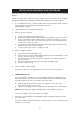
INSTALLATION SEQUENCE AND PROCEDURE Installation must be to Local and National Wiring Regulations and carried out by a Qualified Engineer. Having ensured all space requirements and regulations have been satisfied for the combined arrangement (AGA Cooker & Module), the build and installation is to proceed as follows:1. It is essential that the base or hearth on which both cooker and module stands should be level and capable of supporting the total weight of both units. Module weight = 129 kgs. 2.
8. Make final gas connection to the cooker (15mm compression) into the combined gas cock/pressure test fitting (See Fig. 7). Check for gas tightness after connecting the gas supply. 9. PRESSURE TESTING The pressure test point is situated at the rear left hand side of the appliance just below hotplate level. (See Fig. 7). Remove screw from pressure test nipple. Fit the pressure gauge onto the pressure test nipple. Turn the gas cock to the ON position.
REMOVE 2 FIXING SCREWS DESN 511645 FIG. 3 (WOK BURNER ONLY) DESN 511646 FIG.
FIG.
NOTE: A special rubber grommet is provided to fill-in the ‘knock-out’ hole in the side panel. Pierce the centre of the grommet and pass the 1/4” gas supply pipe through it. Fig 5A - AGA GC3 (Open Flue) & GC3 Power Flue Only - Gas Supply Connections (approximate positions) DESN 512449 DESN 511254 FIG.
DESN 511648 FIG. 7 FROM SURFACE OF THE AGA TO LUGS ON FRONT PLATE OF MODULE 64 TOP PLATE OF MODULE REMOVED DESN 511255 FIG.
BURNER CAP RETAINING LUGS Fig. 9A DESN 511617 Fig.
SERVICING z In the event of your appliance requiring maintenance please call AGA Service or contact your authorised distributor/stockist. z Your cooker must only be serviced by a Qualified Engineer from an authorised distributor or stockist. z Do not alter or modify the cooker. z Only the spares specified by the manufacturer are to be fitted.
AGA ELECTRIC MODUILE GAS HOB (FFD) WIRING DIAGRAM COLOUR KEY BL WH R BK Y PK BR P GR NOTE: 1. IGNITION SWITCHES AND THERMOSTATS ARE SHOWN IN THE OFF POSITION WITH THE APPLIANCE COLD AND FAN OVEN DOOR CLOSED. 2. THE COOKER IS COLD (IE.
For further advice or information contact your local AGA Specialist With AGA’s policy of continuous product improvement, the Company reserves the right to change specifications and make modifications to the appliance described and illustrated at any time Manufactured by AGA Station Road Ketley Telford Shropshire TF1 5AQ England www.aga-web.co.uk www.agacookshop.co.uk www.agalinks.