Electric Range Service Instructions This book contains many important safety messages. Always read and obey all safety messages. F107511-01 www.aga-ranges.
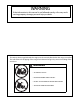
WARNING If the information in this manual is not followed exactly, a fire may result causing property damage, personal injury or death. WARNING The anti-tip device supplied with this range must be correctly fitted when the range is installed.
SERVICING WARNING Disconnect from electricity before servicing. Check appliance is safe when you have finished.
SERVICING WARNING Disconnect from electricity before servicing. Check appliance is safe when you have finished.
SERVICING WARNING Disconnect from electricity before servicing. Check appliance is safe when you have finished.
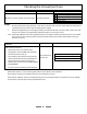
Checking the Multifunction Oven Result Check 1 Open the oven door and turn on the oven light Possible Cause Light does not work 1 No power to range 2 3 4 Light bulb failed (most likely cause) Fault in power supply to switch Faulty switch Action 1 Are other parts of the range working - is the clock on, do the ovens and oven neons work? If not then there is probably no power to the range. Investigate power supply. 2 Remove the light bulb (see ‘Servicing Procedures’).
Checking the Multifunction Oven 7
Checking the Convection Oven Check 1 Open the oven door and turn on the oven light Result Possible Cause Light does not work 1 No power to range 2 3 4 Light bulb failed (most likely cause) Fault in power supply to switch Faulty switch Action 1 Are other parts of the range working - is the clock on, do the ovens and oven neons work? If not then there is probably no power to the range. Investigate power supply. 2 Remove the light bulb (see ‘Servicing Procedures’).
Checking the Convection Oven 9
Servicing Procedures Contents 1. To change oven light bulb. 12 2 How to Move the Range for Servicing 12 3. To Remove a Side Panel 13 4. To Lift up the Ceramic Hob 14 5. To replace a hob element. 15 6. To replace the cooktop neon indicator lights pack 15 7. To Remove the Control Panel 16 8. To Remove Oven Light Switch 16 9. To Remove Oven indicator neon Light 17 10. To Remove Electronic Timer 17 11. To Remove a Thermostat 18 12. To Change Cooktop or Broiler Controller 19 13.
SERVICING WARNING Disconnect from electricity before servicing. Check appliance is safe when you have finished. Servicing Notes Disconnect from electricity supply before commencing servicing, particularly before removing any of the following: control panel, side panels, ceramic hob, or any of the electrical components or cover boxes. Before electrical reconnection check that the appliance is electrically safe. 1. To change oven light bulb.
SERVICING WARNING Disconnect from electricity before servicing. Check appliance is safe when you have finished. Do not move the range by pulling the door handles or knobs. Lift the front slightly and slide the range forward to disengage from the anti-tip bracket. Move the range a bit at a time, checking behind it to make sure the electric cord is not caught.
SERVICING WARNING Disconnect from electricity before servicing. Check appliance is safe when you have finished. 4. To Lift up the Ceramic Hob Pull the range forward. Pull off the push fit control panel end caps at each end and remove the end fixing screws under the end cap. Remove the lower front retaining screws (one each side) situated beneath the lower edge at the front corners of the side panels.
SERVICING WARNING Disconnect from electricity before servicing. Check appliance is safe when you have finished. 5. To replace a hob element. Lift up the ceramic hob see 4. The elements are now accessible. Remove the screw in the center of the element and slide it out to the side. Disconnect wiring from the element – make a note of the wire colors and terminal connections. Refer to the wiring schematic. Fit new elment and reassemble in reverse order.
SERVICING WARNING Disconnect from electricity before servicing. Check appliance is safe when you have finished. 7. To Remove the Control Panel Turn off the power at the circuit breaker. Remove the handrail by first removing the 2 plastic screw cover plugs and then the end bracket fixing screws beneath the plugs. Remove the two screws that were hidden beneath the hand rail end brackets. Pull off the push fit control panel end caps at each end and remove the end fixing screws under the end cap.
SERVICING WARNING Disconnect from electricity before servicing. Check appliance is safe when you have finished. 9. To Remove Oven indicator neon Light Remove control panel (see 7). NB The old indicator neon may be destroyed during removal. Disconnect the wires from the rear of the neon. The light can then be removed by folding back its locking ‘wings’ and pushing forward.
SERVICING WARNING Disconnect from electricity before servicing. Check appliance is safe when you have finished. 11. To Remove a Thermostat Lift up the cooktop - see 4. Remove the control panel - see 8 Remove the oven shelves. Undo the range rear cover screws and lift covers clear. Right Hand oven From inside the oven remove the two fixings that secure the thermostat phial cover. Push the thermostat sensing bulb back to free it from the clips in the oven back panel.
SERVICING WARNING Disconnect from electricity before servicing. Check appliance is safe when you have finished. 12. To Change Cooktop or Broiler Controller Lift up the ceramic hob top (see 4). Remove control panel (see 8). Disconnect wiring from controller – make a note of the wire colors and terminal connections. Refer to the wiring schematic. Remove 2 screws holding controller to mounting panel. Fit new controller and reassemble in reverse order.
SERVICING WARNING Disconnect from electricity before servicing. Check appliance is safe when you have finished. 14 To Adjust the Oven Door Angle The oven doors are heavy. Transit of the range can cause the oven doors to move so that they are not correctly aligned. Both oven doors are fitted with adjustable door bottom hinges. The hinges can be adjusted to alter the angle of the door.
SERVICING WARNING Disconnect from electricity before servicing. Check appliance is safe when you have finished. 15. To Change Oven Door Outer Panel Remove the two plastic blanking plugs from the door handles. Remove the 4mm Hex headed screws holding the handle to the door with the hexagon key tool. Remove two screws from top edge and two from bottom edge of the door. Remove outer door panel - 4 screws. Fit door handle to new panel. Fit the plastic blanking plugs to the fixing holes.
SERVICING WARNING Disconnect from electricity before servicing. Check appliance is safe when you have finished. 17. To Remove the Oven Door Seal Open oven door. The seal is held in place by small hooks on the rear face. At the corner pull seal diagonally away from the door centre until that hook is released. Proceed to the next hook and release it in a similar way, and so on. Use force if the hooks are stiff, as the old seal will be discarded. When fitting new seal, position the seal join at the bottom.
SERVICING WARNING Disconnect from electricity before servicing. Check appliance is safe when you have finished. 20. To Remove an Oven Inner Back Open the oven door. For the left hand oven unscrew the 2 thermostat phial fixing screws. See section 11 ‘To Remove a Thermostat’ for more detail on the thermostat phial fixing screws. Remove the screws that secure the inner back to the oven rear. Lift the removable panel away. Re-assemble in reverse order. Ensure that the retaining screws are fully tightened.
SERVICING WARNING Disconnect from electricity before servicing. Check appliance is safe when you have finished. 23 . To Remove the Left Hand Multifunction Oven Bottom and Top Elements Bottom Element Pull the range forward to access the rear of the range, see the section ‘How To Move the Range for Servicing’. Remove the screws that secure the right hand (when viewed from the rear) cover and lift it clear. Remove the 2 screws ‘A’ and allow the plate to drop down.
SERVICING WARNING Disconnect from electricity before servicing. Check appliance is safe when you have finished. Technical Data INSTALLER: Please leave these instructions with the User. DATA BADGE LOCATION: Under the Main oven. Remove the plinth by pulling forward (it is held in place by magnetic catches) and pull forward on the sheet metal tag under the center of the oven to swing out the badge plate. Dimensions Overall height (splash not fitted) minimum 35 3/8” (89.8 cm) maximum 36 7/16” (92.
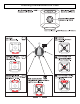
Schematic diagram of the Range Caution: Label all wires prior to disconnection when servicing controls. Wiring errors can cause improper and dangerous operation. Verify proper operation after servicing.
Schematic diagram of the Range Caution: Label all wires prior to disconnection when servicing controls. Wiring errors can cause improper and dangerous operation. Verify proper operation after servicing.
Aga Ranges 110 Woodcrest Road Cherry Hill, NJ 08003 USA 1.866.4AGA.4USA www.aga-ranges.com Email support@aga-ranges.