LITTLE WENLOCK GAS STOVE This appliance is hot while in operation and retains its heat for a long period of time after use. Children, aged or infirm persons should be supervised at all times and should not be allowed to touch the hot work- ing surfaces while in use or until the appliance has thoroughly cooled. INSTALLATION AND OPERATION INSTRUCTIONS To ensure safety, satisfaction and reliable service this stove should be installed by a suitably qualified and competent person.
TABLE OF CONTENTS PAGE NO. 1. Operation Instructions . . . . . . . . . . . . . . . . . . . . . . . . . . . . . . . . . . . . . . . . . . . . . . . . . . . 2 2. Precautions . . . . . . . . . . . . . . . . . . . . . . . . . . . . . . . . . . . . . . . . . . . . . . . . . . . . . . . . . . . 2 3. Lighting . . . . . . . . . . . . . . . . . . . . . . . . . . . . . . . . . . . . . . . . . . . . . . . . . . . . . . . . . . . . . . 2 4. What to do if you smell gas 5. Vent Safety Shut Off Switch . . . . . .
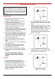
OPERATION INSTRUCTIONS WARNING: Fig. 1 Do not operate the stove with the appliance door open, or if the glass panel in the front door has been broken or removed. that the door latch is fully locked. Ensure Keep the door spin valve closed at all times when stove is in operation. PRECAUTIONS 1. Do not touch any part of the stove while in 2. Children and adults should be alerted to the 3. operation, except the controls. 3. hazzards of surface temperatures.
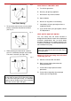
Fig.4 WHAT TO DO IF YOU SMELL GAS Low Flame Setting 7. A. Turn off the gas mains. B. Do not try to light any appliance. C. Do not touch any electrical switch. D. Open windows. E. Do not use any phone in the building. F. Immediately call your gas engineer from a G. If you cannot reach your gas supplier, call the To turn off the main burner, turn the control knob in a clockwise direction to low flame. (see Fig. 4) Fig. 5 neighbours phone. Fire Department.
TECHNICAL DATA GENERAL Pressure Setting From Cold Natural Gas Inlet Pressure = Product Identification No.: viduals I2E, G20, 20 mbar/8” wg & The = 7.4”/18.5 mbar imperative Maximum flow rate Minimum flow rate Burner: = system should be More that control circulating air compartments, passageways of It is burners the room It this manual. NOTE: 3 37.78 MJ/m Before installation, check that the local distribution 3 0.
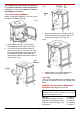
This appliance has been tested and approved Fig.9 in accordance with the essential requirements of Annex 1 in the Gas Appliance (90/396/EEC) as amended. Directive PRE- INSTALLATION ASSEMBLY Before installing the appliance carry out the following pre-installation assembly: Fig.7 3. Ensure the leads to the vent safety shut off switch located on the back of the stove are connected and secure. (See Fig. 10). Fig.10 1. Open the fire door (item 9), and remove 2.
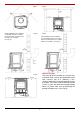
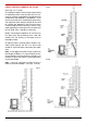
Fig.14 Fig.11 When installing the stove against a combustible wall leave a 6” space Fig.12 Fig.15 between the back of the stove and When installing the stove against a the wall for air circulation. non-combustible wall leave a 2” space (See Fig.12) between the back of the stove and the wall for air circulation. (See Fig.15) HEARTH FITTING Fig.13 This stove MUST be installed on a concrete con- structional hearth, or on a non-combustible hearth slab, minimum size 27.5” (500mm) x 28.
Fig.16 Fig.17 The chimney and flue pipes intended for use with this appliance should be mechanically robust, resistant to internal and external corrosion, non- combustible, and durable under the conditions to which they are likely to be subjected. WARNING: nected to a lation Only operate this appliance if conproperly chimney system.
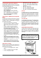
USE OF EXISTING CHIMNEYS AND FLUES Fig.19 (See Figs. 18, 19 & 20) An existing flue pipe or chimney that has proved to be satisfactory when used for solid fuel can normally be used for a gas appliance provided that its construction and condition is acceptable. Flues that have proved to be unsatisfactory, particularly with regard to down draught, should not be used for venting gas appliances until they have been examined and any faults corrected.
* FACTORY-MADE INSULATED CHIMNEY’S * Factory-made insulated chimneys must be con- * structed and tested to meet the relevant standards and recommendations given in: * B.S. 7566: * * Installation of factory made * chimney’s conforming to B.S. : 4543 for * domestic appliances. Part 1: Method of specifying installation Part 2: Specification for installation design. Part 4: Recommendation for installation B.S. 4089 - L.P.G. hoses and assemblies.
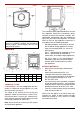
WARNING: To avoid pipe sealing PLACEMENT OF COALS compounds from entering into the gas train, do not apply seal- WARNING: ing compound to the first two threads at the tip of stove the gas connection. are The ceramic coals supplied with this extremely durable and long lasting when fitted properly. They are, however, very del- icate and can be easily damaged if they are not Fig.22 handled very carefully. Handling damage to the ceramic coals is not covered by warranty. 1.
4. 5. Place 4 medium coals on the front of the Lay the two remaining medium coals random- one corner of each coal resting on a spar. one corner of the coals touch any other coal. matrix with their corners touching and also ly on the matrix ensuring that no more than (see Fig.26) (See Fig. 29) Fig.26 Fig.29 Place 4 large coals on the rear of the matrix with their corners touching. The front corner should over hang the back section of the matrix by approximately 10mm. (See Fig.
WARNING: Do not operate the stove with the Fig.31 appliance door open, or if the glass panel in the CORRECT FLAME INCORRECT FLAME front door has been broken or removed. Ensure the door latch is fully locked. Keep the door spin valve closed at all times when the stove is in operation. During the first light up period an odour will rise from the stove, this is due to the materials in the stove drying and curing.
Fig.38 Fig.33 Fig.34 Changing of Burner Injector Orifice With the complete burner assembly removed as per Fig. 35, 36, 37. 1. Disconnect the 6mm gas feed pipe from the 2. Slacken the 6mm gas feed pipe to the 3. control to injector. (see Fig. 38). injector at the control. Remove Injector from burner. Removal of Pilot Burner 1. Fig.35 2. Unscrew the two pilot burner. 1 /4” slotted head screw from (See Fig.39) Disconnect the 6mm gas feed pipe. Fig.39 ENAMEL CLEANING Fig.
LITTLE WENLOCK GAS EXPLODED VIEW 1. 2. 3. 4. 5. 34 6. 7. 8. 9. 10. 11. 12. 13. 14. 35 15. 16. 17. 18. 19. 39 36 20. 37 Leg 21. Front Frame 22. Blanking Plate 23. Flue Spigot Hob Back Casting Burner NG 26. Aga Stove Badge 28. 1/4” BSP Nut 29. Mains Inlet Bracket 30. Vent Switch Bracket 31. Rating Plate Bracket 32. Vent Switch 33. Coal Matrix 34. Door Assembly 35. Control Plate 36. Serial Number Plate 37. Data Plaque 38. Front Baffle 39.
TROUBLE SHOOTING GUIDE PROBLEM POSSIBLE CAUSE SOLUTION Pilot will not light No gas Check gas is turned on. Safety interlock preventing Operation. Control knob not fully pressed. Ensure control knob is being fully Disconnected piezo igniter. Connect piezo cable. Insufficient gas pressure. Call your qualified service technician. Blocked orifice. Call your qualified service technician. Air in gas lines Damaged pilot hood. Defective control valve.