Masterchef II Ceramic Deluxe User's Manual & Installation and Servicing Instructions PLEASE READ THESE INSTRUCTIONS BEFORE USING THIS APPLIANCE For use in GB and IE 04/09 EINS 515222
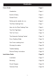
Contents Users Guide Page 3 Introduction Page 4 Health & Safety Page 4 Control Panel Page 5 Setting up the cooker for use Page 6 The Slow Cooking Oven Page 7 Ideas for the Slow Cooking Oven Page 8 The Grill (Top Right) Page 12 The Fan Ovens Page 13 The Automatic Cooking Control Page 14 Oven Cooking Guide Page 16 Fan Ovens cooking chart Page 19 Cleaning the cooker Page 20 Troubleshooting Page 22 General Safety Instructions Page 23 Installation Guide Page 25 Installation Page
Users Guide 3
Introduction Health & Safety As responsible manufacturers we take care to make sure that our products are designed and constructed to meet the required safety standards when properly installed and used. APPLIANCE: YOUNG CHILDREN SHOULD BE KEPT AWAY FROM THE APPLIANCE AS SOME SURFACES CAN BECOME HOT TO TOUCH. IMPORTANT NOTICE: PLEASE READ THE ACCOMPANYING WARRANTY.
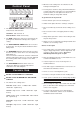
Control Panel z When the hob cooking areas are switched on, the heating area will glow red. z The hot plates contain a safety switch which limits the ceramic temperature if the plates are operated without a pan in position, or if the plates have been at a maximum setting for longer than normal. To get the best out of your hob z z Ensure that the pan covers the heating area. z Switch off the plates when the cooking is complete. z Do not cook directly on the hob surface. Always use a pan.
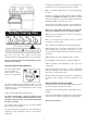
Setting up the cooker for use Before the fan oven can be used, it will be necessary to set the ‘time-of-day-clock’. This is a 24-hour clock, and when the power supply is initially switched on, or after an interrruption in supply, the clock will show 12.00 and the LED bar 4 will flash above the sign. SETTING THE TIME OF DAY 1. Whilst the LED bar 4 day. is flashing, press the plus + and/or minus buttons until the display shows the correct time of 2. After 5 seconds, the bar 4 will stop flashing.
Push dishes well back in the oven to ensure that they are positioned over the element beneath the base plate. Make sure all dishes will fit into the oven before preparing the food. All dishes cooked by the slow cooking method should be cooked for a minimum of 6 hours. They will ‘hold’ at this setting for a further 1-2 hours but marked deterioration in appearance will be noticed in some cases. Joints of meat and poultry should be cooked at 180°C for 30 minutes before transferring to the slow cooking oven.
Ideas for the Slow Cooking Oven Many favourite recipes can be adapted for this type of cooking: Slow Cooking Oven Recipes - Meal 1 6 - 8 hours cooking time Ragout of Beef in Ale Baked Potatoes Rice Pudding Ingredients Method Ragout of Beef in Ale 30ml (2tbsps) oil 675g (1 1/2 lbs) chuck steak, cubed 1 clove of garlic, crushed 2 carrots, sliced 100g (4oz) mushrooms, quartered 2 medium onions, sliced 40g (1 1/2 ozs) plain flour 5ml (1 tsp) coarse-grained mustard 10ml (1 dsp) Demerara sugar 30ml (2tbsps)
Slow Cooking Oven Recipes - Meal 2 6 - 8 hours cooking time Roast Fillet of Lamb Dauphinoise Potatoes Bread and Butter Pudding Ingredients Method Roast fillet of Lamb 900g - 1.25 kg (2 - 2 1/2lbs) lamb 1. Season and wrap the lamb in foil. 2. Stand meat on a rack over a small roasting tin. Dauphinoise Potatoes 1. Grease a shallow oval or rectangular dish. 450g (1 lb) potatoes, thinly sliced 1-2 cloves of garlic, crushed 125ml (1/4 pt) double cream salt and freshly ground black pepper 2.
Slow Cooking Oven Recipes - Meal 3 6 - 8 hours cooking time Gammon and Apricot Pie Braised Red Cabbage St. Clements Pudding Ingredients Method Gammon and Apricot Pie 2 gammon rashers approx 15mm (1/2”) thick 100g (4oz) no-soak dried apricots 25g (1oz) sultanas 3 large potatoes, thinly sliced 300ml (1/2 pt) chicken stock 50g (2oz) butter, melted 1. Remove the rind from the gammon. Nick the edges and lay them in a shallow dish. 2. Sprinkle with apricots, sultanas and pepper. 3.
Slow Cooking Oven Recipes - Meal 4 6 - 8 hours cooking time Chilli Con Carne Oven Rice Frangipane and Apple Pudding Ingredients Method Chilli Con Carne 450g (1 lb) minced beef 1 x 400g (14 oz) tin tomatoes 1 x 400g (14oz) tin kidney beans 1 packed Chilli con carne spice mix 100ml (4 fl oz) water 1. Brown the minced beef in an oval casserole dish. 2. Stir in the spice mix. 3. Add beans drained, tomatoes and water. 4. Mix well together. Bring to boil, cover well and place in oven.
Most food is cooked at a high setting but for thicker pieces of meat/poultry and for food such as well done steak the heat can be reduced by turning the control down to a lower setting. For best results pre-heat at a high setting for approximately 2 minutes. The Grill (Top Right) CAUTION: Accessible parts may be hot when the grill is in use. Young children should be kept away. The grill pan fits on the shelf supplied (shown out of the grill chamber for clarity).
NOTE: The recommended cooking temperatures for fan ovens are generally lower than non-fanned ovens. (See Page 16). Turn the oven temperature knob to the temperature you need. The oven indicator light will glow until the oven has reached the temperature you selected. It will then cycle on and off during cooking. The Fan Ovens During use the appliance becomes hot. Care should be taken to avoid touching the heating elements inside the ovens.
The Automatic Cooking Control To Set an Automatic Cooking Programme This control includes a minute timer, a time-of-day clock as well as an automatic cooking control. The STOP time or cooking time can be entered first. Each setting will remain displayed for 5 seconds, before changing back to displaying the time of day. There are three buttons which operate the timer. The buttons are used for the following purposes.
Setting a Stop Time Only 1. Place the food on the correct shelves in the oven. 2. Press the MODE button repeatedly until the LED bar 3 flashes and then press the plus + button until the time at which the cooking is to end. After 5 seconds the LED will stop flashing. 3. Set the oven temperature control. Cooking will start immediately. 4. At the of the cooking time, a beep will sound and will continue for 2 minutes unless cancelled manually. This can be cancelled by pressing any of the buttons. 5.
Steam Oven Cooking Guide When cooking foods with a high water content (e.g. oven chips) there may be some steam visible at the grille at the rear of the hotplate. Cooking Hints When using the fan ovens, reduce conventional oven settings by 10ºC - 20ºC and cooking time by up to 10 minutes for every hour. Condensation may form on the cooker. This is quite normal and nothing to worry about. The condensation forms when heat and moisture are present.
The Fan Oven shelves To re-fit the shelf, hold it so that it is slightly up at the front and rest the back of the shelf on the side wires. Push the shelf to the back of the oven and then lower the front so that it is resting on the side wires. The shelves should not be fitted directly one above the other. When cooking on more than one shelf always leave at least one runner space between them. The oven shelves are retained when pulled forward but can easily be removed and re-fitted.
The oven control settings and cooking times given in the table are intended to be used only as a guide. Individual tastes may require the temperature to be altered to provide a preferred result. There may be a slight difference in the results between the two ovens. This is due to manufacturing tolerances and it may be necessary to alter times and temperature settings to allow for this. Food is cooked at a lower temperature in a fan oven than in a conventional oven.
Fan oven cooking chart FOOD SETTING ºC APPROXIMATE COOKING TIME FISH Whole Fish e.g. trout, mackerel 170 25 - 30 mins depending on size Steaks 170 20 - 25 mins depending on thickness Oven-fried fish 210 25 mins depending on packet instructions Salmon (2.
The shelf is designed to lock in place, but is removable for cleaning. To remove, lift up at the front then pull forward. Cleaning the cooker The grill pan and rack should be washed in hot soapy water. Essential Information Before thorough cleaning isolate the electricity supply. Remember to switch on the electricity supply before use. After grilling meat or any food that soils, leave the grill pan to soak for a few minutes in the sink immediately after use.
Cleaning Table Outside of cooker Part Door, door surround Door front frame Finish Recommended Cleaning Material Enamel or paint Hot soapy water, soft cloth. Any stubborn stains, remove gently with a liquid detergent. Sides Painted surface Hot soapy water, soft cloth Rear grille, plinth Enamel or Paint Hot soapy water, soft cloth. Cream cleaner, with care if necessary. Control panel Enamel Warm soapy water. Do not use abrasive cleaners on lettering.
Oven temperature getting hotter as the cooker gets older If turning the knob down has not worked or only worked for a short time then the cooker may need a new thermostat. This should be fitted by a service person. Troubleshooting Steam is coming from the oven When cooking foods with a high water content (e.g. oven chips) there may be some steam visible at the rear grille. Take care when opening the oven door, as there may be a momentary puff of steam when the oven door is opened.
Do not spray aerosols in the vicinity of the cooker while it is on. General Safety Instructions Do not store or use combustible materials, or flammable liquids in the vincinty of this appliance. The installation must be in accordance with the installation instructions and comply with the relevant regulations and also, the local electricity supply companies requirements. This appliance is designed for domestic cooking only. Use for any other purpose could invalidate any warranty or liability claim.
Do not use aluminium foil to cover shelves, linings or the oven roof. Never heat unopened food containers. Pressure build-up may make the container to burst and cause injury. The cooker is designed for cooking foods only and must not be used for any other purpose. The oven should NOT be used for heating the kitchen. This wastes fuel and the controls knobs may become overheated. When the oven is on DO NOT leave the door open for longer than necessary. The specification of this cooker should not be altered.
Installation Section Remember, when replacing a part on this appliance, use only spare parts that you can be assured conform to the safety and performance specification that we require. Do not use reconditioned or copy parts that have not been clearly authorised by Aga.
Dear Installer Before you start your installation, please complete the details BELOW. If your customer has a problem relating to your installation they will be able to contact you easily. Thank you Installer's Name Installer's Company Installer's Telephone number You will only need the following equipment to complete the cooker installation satisfactorily. MULTIMETER (for electrical checks) Make sure the installation is electrically safe. You will also need the following tools: 1. 2. 3. 4. 5.
Installation For non-combustible surfaces (such as unpainted metal or ceramic tiles) this can be reduced to 25mm. WARNING: THIS APPLIANCE MUST BE EARTHED A minimum space of 650mm is required between the top of the hob and a horizontal combustible surface. This appliance is designed for the voltage stated on the data plate, which is situated in the right hand lower corner under the plinth plate. Any cooker hood should be installed in accordance with the hood manufacturers instructions.
Fit splashback as shown. To raise the cooker turn screw clockwise, to lower turn screw anti-clockwise. Fitting a stability bracket A stability bracket (not supplied with the cooker) should be fitted. Any restraining device should be secured to the fabric of the building and should also be released so that the cooker can be pulled out for cleaning and maintenance. When fitting a stability bracket read these instructions together with the leaflet supplied with the bracket.
Electrical Connection This appliance must be installed by a qualified electrician to comply with the relevant regulations and also the local electricity supply company requirements. WARNING: THIS APPLIANCE MUST BE EARTHED. NOTE: The cooker must be connected to the correct electrical supply as stated on the voltage label on the cooker, through a suitable cooker control unit incorporating a double pole switch having a contact separation of at least 3mm in all poles.
SERVICING - WARNING Disconnect from electricity before servicing. Check appliance is safe when you have finished B. To Remove Side Panels 1. Isolate from electric supply. 2. Lower front mobility wheels see section ‘Levelling’ page 27, in the Users instructions. 3. Remove fixing screws and lift off side panel. 4.
SERVICING - WARNING Disconnect from electricity before servicing. Check appliance is safe when you have finished E. To Remove Grill Element 1. Isolate from electric supply. 2. Remove two screws securing grill pelmet and remove pelmet. 3. Remove two screws securing grill element fixing to carrier to grill cavity and allow element and carrier to hinge down from the rear. 4. The element can now be lifted out of the carrier to allow access to the electric terminals at the rear. 5.
SERVICING - WARNING Disconnect from electricity before servicing. Check appliance is safe when you have finished L. 1. 2. 3. 4. 5. 6. 7. J. 1. 2. 3. 4. 5. To Remove Oven Fan Isolate from electric supply. Proceed as ‘TO REMOVE OVEN ELEMENT’. Remove 4 fixing screws securing fan assembly to frame. Withdraw fan assembly sufficiently to gain access to motor electrical terminals and disconnect cables. Remove fan blade. NOTE: Fan blade fixing nuts is LH thread. Remove motor from mounting plate screws.
SERVICING - WARNING Disconnect from electricity before servicing.
A1 A2 A3 A4 A5 A6 B C D F G H1 H2 M O P I J K Q R1 R2 S T U1 U2 U3 V Y X Grill energy regulator Front LH dual energy regulator Rear LH energy regulator Central dual energy regulator Rear RH energy regulator Front RH energy regulator Grill element Central hob element Slow cooking oven thermostat Slow cooking oven element Oven light switches Right hand oven light Left hand oven light Left hand oven thermostat Left hand oven element Left hand oven fan Right hand oven thermostat Right hand oven fan Right hand
Technical Data INSTALLER: Please leave these instructions with the User. DATA BADGE LOCATION: Behind plinth panel, serial number repeater badge below right hand oven opening.
For further advice or information contact your local distributor/stockist With Aga’s policy of continuous product improvement, the Company reserves the right to change specifications and make modifications to the appliance described and illustrated at any time. Manufactured By Aga Station Road Ketley Telford Shropshire TF1 5AQ England www.aga-web.co.uk www.agacookshop.co.uk www.agalinks.