MASTERCHEF XL USER GUIDE & INSTALLATION INSTRUCTIONS 110 Induction
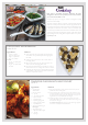
Each piece in the AGA Cookshop collection has been designed to offer the best possible performance, whether you cook with an AGA or not. Developed by experts, our range of cookware is designed for quality, performance and durability. The AGA Cookshop collection comprises cookware, kettles, bakeware, textiles and a variety of accessories.
Contents 1. 2. 3. Before You Start... 1 6. Troubleshooting 21 Installation and Maintenance 1 Peculiar Smells 1 7.
ii
1. Before You Start... Personal Safety Thank you for buying this cooker. It should give you many years of trouble-free cooking if installed and operated correctly. Important information for pacemaker and implanted insulin pump users: The functions of this hob comply with the applicable European standards on electromagnetic interference. If you are fitted with a pacemaker or implanted insulin pump and are concerned please consult your doctor for medical advice.
Always keep combustible materials, e.g. curtains, and flammable liquids a safe distance away from your cooker. Fig.1-1 DO NOT spray aerosols in the vicinity of the cooker nn while it is on. Cooking high moisture content foods can create a ‘steam burst’ when an oven door is opened (Fig.1-1). When opening an oven stand well back and allow any steam to disperse. ArtNo.324-0001 Steam burst Use dry oven gloves when applicable – using damp gloves might result in steam burns when you touch a hot surface.
Hob Care Fig.1-3 NEVER cook directly on the hob surface (Fig.1-2). nn DO NOT use the hob surface as a cutting board. nn Do not leave utensils, foodstuffs or combustible items on the hob when it is not is use (e.g. tea towels, frying pans containing oil). DO NOT place plastic or aluminium foil, or plastic nn containers, on the hob. DO NOT leave the hob zones switched on unless nn being used for cooking. ArtNo.312-0002 Salt cellar onto hob Do not stand or rest heavy objects on the hob.
2. Cooker Overview DocNo.020-0006 - Overview - 100DF - Prof+ Fig.2-1 A B C E D F Your induction cooker (Fig.2-1) has the following features: Fig.2-2 A. B. C. D. E. F. 5 induction cooking zones A control panel A glide-out grill A multi-function oven A slow cook oven A fan oven The Hob Use only pans that are suitable for induction hobs. We recommend stainless steel, enamelled steel pans or cast iron pans with enamelled bases.
Never use a round-bottomed wok, even with a stand. Fig.2-4 The very best pans have bases that are very slightly curved up when cold (Fig.2-3). If you hold a ruler across the bottom you will see a small gap in the middle. When they heat up the metal expands and lies flat on the cooking surface. Max: 1.85 kW Boost: 2.5 kW Max: 1.85 kW Boost: 3.0 kW Max: 1.85 kW Boost: 2.5 kW Make sure that the base of the pan is clean and dry to prevent any residue burning onto the hob panel.
Residual Heat Indicator, H Power level Automatic heat-up time at 100% (min:sec) 1 0:48 2 2:24 3 3:50 4 5:12 5 6:48 Automatic Heat-up, A 6 2:00 7 2:48 8 3:36 This function is available on all of the cooking zones. It allows rapid heating up of the element to bring the selected cooking zone up to temperature. Once the zone is at the required cooking temperature the power level will reduce automatically to the preset level.
Low Temperature Setting, L1/L2 • • Fig.2-8 A & B linked Each cooking area is equipped with 2 low temperature settings: L1 will maintain a temperature of about 40 °C – ideal for gently melting butter or chocolate. L2 will maintain a temperature of about 90 °C – ideal for simmering (bring the pan to the boil and then select L2 to keep soups, sauces, stews, etc at an optimal simmer). A B D The maximum time this setting can be used is 2 hours.
The Glide-out Grill Fig.2-9 Caution: This appliance is for cooking purposes nn only. It must not be used for other purposes, for example room heating. Caution: Accessible parts may be hot when the grill nn is in use. Young children should be kept away. Open the door and pull the grill pan carriage forward using the handle (Fig.2-9). The grill has two elements that allow either the whole area of the pan to be heated or just the right-hand half. To heat the whole grill, turn the knob clockwise (Fig.2-10).
The Ovens Fan oven cooking is particularly suitable for baking on several shelves at one time and is a good ‘all-round’ function. It may be necessary to reduce the temperature by approximately 10 °C for recipes previously cooked in a conventional oven. The clock must be set to the time of day before the lefthand oven will work. See the following section on ‘The Clock’ for instructions on setting the time of day.
Base Heat The Fan Oven This function uses the base element only. It will crisp up your pizza or quiche base or finish off cooking the base of a pastry case on a lower shelf. It is also a gentle heat, good for slow cooking of casseroles in the middle of the oven or for plate warming. The right-hand oven is a fan oven that circulates hot air continuously, which means faster, more even cooking. The recommended cooking temperatures for a fan oven are generally lower than a conventional oven.
Operating the Ovens Fig.2-12 Fan Oven Turn the oven knob to the desired temperature (Fig.2-12). The oven indicator light will glow until the oven has reached the temperature selected. It will then cycle on and off during cooking. Multi-function Oven The multi-function oven has two controls: a function selector and a temperature setting knob (Fig.2-13). Turn the function selector control to a cooking function. Turn the oven temperature knob to the temperature required (Fig.2-14). Fig.
Fig.2-16 The Clock ArtNo.300-0004 2-button clock annotated Setting the Time of Day The 2-knob LCD clock is shown in (Fig.2-16). When the clock is first connected, the display flashes ( 0.00 ) and ( alternately. ) A To set the time, turn and hold the Timer knob to the clock symbol [] and at the same time turn the Adjusting knob left or right until the clock shows the time of day. Remember this is a 24-hour clock. Let go of the Timer knob and it will spring back to the vertical, oven manual setting.
The ‘stop time’ is displayed, followed by ‘AUTO’. Set the oven to the cooking temperature you need. Turn the Timer knob to the ‘Auto’ setting. Fig.2-24 Fig.2-25 Art No. 301-0011 2BC Activating the key lock 1 When your cooking is finished, the beeper sounds. Turn the Timer knob to the vertical [] to return to manual cooking. ArtNo.301-0012 2BC Activating the key lock 2 If you are out, do not worry about the beeper going off – it stops on its own after a while.
Accessories Fig.2-29 Flat shelf Oven Shelves Shelf guard In addition to the flat shelves, your cooker is supplied with a drop shelf (Fig.2-29). The drop shelf increases the possibilities for oven shelf spacing. Front Drop shelf The oven shelves can be easily removed and refitted. Pull the shelf forward until the back of the shelf is stopped by the shelf stop bumps in the oven sides (Fig.2-30).
3. Cooking Tips DocNo.030-0010 - Cooking tips - 110 induction GENERIC Hints on Using Your Induction Cooker General Oven Tips If you have not used an induction cooker before please be aware of the following: The wire shelves should always be pushed firmly to the back of the oven. • Baking trays with food cooking on them should be placed level with the front edge of the oven’s wire shelves. Other containers should be placed centrally.
4. Cooking Table DocNo.031-0004 - Cooking table - electric & fan single cavity The oven control settings and cooking times given in the table below are intended to be used as a guide only. Individual tastes may require the temperature to be altered to provide a preferred result. Food is cooked at lower temperature in a fan oven than in a conventional oven. When using recipes, reduce the fan oven temperature by 10 °C and the cooking time by 5-10 minutes.
5. Cleaning Your Cooker Isolate the electricity supply before carrying out any major cleaning. Allow the cooker to cool. Fig.5-1 Never use paint solvents, washing soda, caustic nn cleaners, biological powders, bleach, chlorine based bleach cleaners, coarse abrasives or salt. Do not mix different cleaning products – they may nn react together with hazardous results. All parts of the cooker can be cleaned with hot soapy water – but take care that no surplus water seeps into the appliance. ArtNo.
Glide-out Grill Fig.5-2 Before you remove any of the grill parts for cleaning. nn make sure that they are cool, or use oven gloves. The grill pan and trivet should be washed in hot soapy water. Alternatively, the grill pan can be washed in a dishwasher. After grilling meats or any foods that soil, leave to soak for a few minutes in the sink immediately after use. Stubborn particles may be removed from the trivet by using a nylon brush.
Control Panel and Doors Fig.5-6 Avoid using any abrasive cleaners including cream cleaners. For best results, use a liquid detergent. The same cleaner can also be used on the doors, or alternatively, using a soft cloth wrung out in clean hot soapy water – but take care that no surplus water seeps into the appliance. After cleaning, polish with a dry cloth. Ovens ArtNo.
Cleaning Table Cleaners listed (Table 5-1) are available from supermarkets or electrical retailers as stated. For enamelled surfaces use a cleaner that is approved for use on vitreous enamel. Regular cleaning is recommended. For easier cleaning, wipe up any spillages immediately. Hotplate Part Finish Recommended Cleaning Method Hob Top Enamel or stainless steel Hot soapy water, soft cloth. Any stubborn stains remove gently with a nylon scourer.
6. Troubleshooting DocNo.050-0001 - Troubleshooting - Induction GENERIC The cooling fan The induction hob incorporates a cooling fan. This cooling fan is active when either the grill or ovens are on. Under certain conditions, the cooling fan may remain active when the grill or ovens are switched off. This is normal and the fan will switch off automatically. Interference with and repairs to the hob MUST NOT nn be carried out by unqualified persons.
Food is cooking too slowly, too quickly, or burning Cooking times may differ from your previous oven. Check that you are using the recommended temperatures and shelf positions – see the oven cooking guide. Then adjust the settings according to your own individual tastes. Fig.6-1 ArtNo.324-0005 Oven light bulb The oven is not cooking evenly Do not use a baking tray with dimensions larger than those specified in the section on ‘General Oven Tips’. Fig.
Taking care to protect your fingers with a glove in case the bulb should shatter, unscrew the old bulb. Fig.6-3 Screw in the new bulb clockwise and then screw the bulb cover back on. Turn on the electricity supply and check that the bulb now lights. The oven door is misaligned The bottom hinge of either oven door can be adjusted to alter the angle of the door (Fig.6-3).
INSTALLATION Check the appliance is electrically safe when you have finished. 7. Installation You will need the following equipment to complete the cooker installation satisfactorily: Dear Installer Before you start your installation, please complete the details below, so that, if your customer has a problem relating to your installation, they will be able to contact you easily. • Multimeter: For electrical checks. You will also need the following tools: 1. Steel tape measure 2.
INSTALLATION Check the appliance is electrically safe when you have finished. Positioning the Cooker Fig.7-1 Fig.7-1 shows the minimum recommended distance from the cooker to nearby surfaces. 75 mm min The cooker should not be placed on a base. 650 mm min 75 mm min The hotplate surround should be level with, or above, any adjacent work surface. A gap of 75 mm should be left between each side of the cooker Above the hotplate level and any adjacent vertical surface.
INSTALLATION Check the appliance is electrically safe when you have finished. Lowering the Two Rear Rollers Fig.7-5 To adjust the height of the rear of the cooker, first fit a 13 mm spanner or socket wrench onto the hexagonal adjusting nut (Fig.7-5). Rotate the nut – clockwise to raise – counterclockwise to lower. Make 10 complete (360°) turns clockwise. Make sure you lower BOTH REAR ROLLERS. Completing the Move Unfold the rear edge of the cardboard base tray.
INSTALLATION Check the appliance is electrically safe when you have finished. Fitting the Handles Fig.7-7 The handles for the grill and slow oven will require fitting as follows: Open the door. To keep the door open, either place a suitable weight on it or have someone hold it. Fit the handle over the studs in the front of the door (Fig.7-7). With the handle in place, fit the nut locating pegs into the handle threaded bolts (Fig.7-8). Slide the retaining nuts over the pegs (Fig.
INSTALLATION Check the appliance is electrically safe when you have finished. Electrical Connection Fig.7-11 The cooker must be installed by a qualified electrician, in accordance with all relevant British Standards/Codes of Practice (in particular BS 7671), or with the relevant national and local regulations.
INSTALLATION Check the appliance is electrically safe when you have finished. Final Fitting Fig.7-13 Fitting the 2-piece Plinth Fit the inner plinth to the bottom front of the cooker using the 5 screws provided (3x M5 screws in the lower edge, 2x No.8 screws in the each end) (Fig.7-13). Inner plinth Loosen the 2 screws in the front of the inner plinth. Locate the 2 slotted brackets on the inside of the outer plinth onto the 2 screws (Fig.7-14).
8. Circuit Diagrams ArtNo.095-0003 - Circuit diagram - 90 induction Circuit Diagram: Hob E 5 4 3 2 1 Induction unit Earth N(6) On terminal block N(4) On terminal block Hob display ArtNo.
Circuit Diagram: Oven K b br r r br br r K bk br B2a br K b br br br bk A1 bk v K r v r b br B1 w b b J A2 bk b B5 br Jb r gr 8 B7 b w B6 y o B2 5 P5 w 4 y 3 o 2 P4 o bk 1 1 P1 br r r bk b K D2 Black Boot D3 b 1 b w F1 L y 4 v o 3 P3 P3 br F2 P2 br 2 br P1 y P2 w P4 F3 v v 1 P038434 br v G2 P1 b P033458 b P1 P033458 P2 y bk 2 br w w y 6 7 P2 P8 v P7 r P6 w o r gr b b br 3 b B3 B4 2 P095199 Black Boot b b v
DocNo.107-0023 - Technical data - 110DF - Classic DL 9. Technical Data INSTALLER: Please leave these instructions with the User. DATA BADGE LOCATION: Cooker back, serial number repeater badge below oven door opening. Country of Destination: GB, IE. Connections Electric 230/400 V 50 Hz Dimensions Overall height minimum 905 mm maximum 930 mm Overall width 1100 mm Overall depth 610 mm to fascia; 685 mm over handles Minimum space above hotplate 650 mm Refer to ‘Positioning the Cooker’.
Notes 33
Notes 34
CUSTOMER SERVICE WARRANTY If you have any product enquiries, or in the event of a problem with your appliance once it has been installed, please telephone 0845 602 3015. An AGA Masterchef XL has a five-year parts and one-year labour warranty. CUSTOMER SERVICE LINES OPEN: Monday to Friday 8am - 5pm Saturday (October - January only) 8:30am - 12pm ALSO PART OF THE AGA COLLECTION...
Station Road Ketley Telford Shropshire TF1 5AQ England Tel: 0845 815 2020 E-mail: customerservicesaga@aga-web.co.uk Consumer Services Tel: +44 (0) 845 712 5207 agaliving.com For ROI Enquiries Tel: 01 663 6166 For International Enquiries Tel: +44 (0) 115 946 6106 Registered in England and Wales. Registration No.