AGA SIX-FOUR SERIES - CERAMIC HOB OWNERS MANUAL DESN 513131 Comprising Servicing, Installation & Users Instructions & Cooking Guide Remember, when replacing a part on this appliance, use only spare parts that you can be assured conform to the safety and performance specification that we require. Do not use reconditioned or copy parts that have not been clearly authorised by Aga.
CONTENTS SECTION PAGE INTRODUCTION PRODUCT VIEW 3 4 INSTALLATION SECTION 5 INSTALLATION TECHNICAL DATA FITTING AND PRODUCT DIMENSIONS ELECTRICAL CONNECTION LEVELLING AND MOBILITY WHEELS SPLASHBACK USERS GUIDE 6 7 8 9 - 10 11 12 13 HEALTH AND SAFETY CONTROL PANEL SETTING UP THE COOKER FOR USE CERAMIC HOB THE GRILL THE OVENS (GENERAL) SIMMERING OVEN SIMMERING OVEN RECIPES OVEN COOKING GUIDE THE MINUTE TIMER AUTOMATIC COOKING CONTROL CLEANING AND CARING FOR YOUR COOKER SERVICING SECTION 14 15 16 17 18
INTRODUCTION As responsible manufacturers we take care to make sure that our products are designed and constructed to meet the required safety standards when properly installed and used. IMPORTANT NOTICE: PLEASE READ THE ACCOMPANYING WARRANTY. Any alteration that is not approved by Aga could invalidate the approval of the appliance, operation of the warranty and could affect your statutory rights. In the interests of safety and effective use, please read the following before using your new Aga appliance.
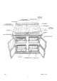
Fig.
Installation Section Remember, when replacing a part on this appliance, use only spare parts that you can be assured conform to the safety and performance specification that we require. Do not use reconditioned or copy parts that have not been clearly authorised by AGA.
INSTALLATION WARNING: THIS APPLIANCE MUST BE EARTHED This appliance is designed for the voltage stated on the data plate, which is situated in the right hand vent slot at the base of the appliance. The Aga Six-Four Series Ceramic Hob is supplied from the manufacturers as a fully tested chassis construction. Ceramic hob, doors, splashback and handrail are assembled during installation.
TECHNICAL DATA HOTPLATE FRONT LEFT - double circuit - 2.2 kW/0.75 kW - 205/120mm dia - rapid heat up REAR LEFT - single circuit - 1.2 kW - 140mm dia - rapid heat up FRONT CENTRE - single circuit - 1.2 kW - 140 mm dia - rapid heat up REAR CENTRE - double circuit - 2.2 kW/0.75 kW - 205/220mm dia - rapid heat up FRONT RIGHT - single circuit - 1.5 kW - 155mm dia - rapid heat up REAR RIGHT - single circuit - 1.5 kW - 155mm dia - rapid heat up ELECTRIC GRILL AND OVENS TOP OVEN - POWER RATING - 2.
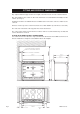
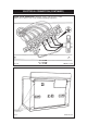
FITTING AND PRODUCT DIMENSIONS Any adjacent walls that project above the height of the hob must be of heat resistant material. Any side wall above the cooker on either side shall not be less than 60mm horizontally from the cooker. (See Fig. 2). A minimum clearance of 1000mm must be available at the front of the cooker to enable it to be serviced. Surfaces over the top of the cooker must not be closer than 650mm. (Cooker Hood, see below). The vent slots in the back of the top plate must not be obstructed.
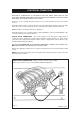
ELECTRICAL CONNECTION ELECTRICAL CONNECTION IS LOCATED AT THE TOP RIGHT HAND SIDE OF THE APPLIANCE, BEHIND SIDE PANEL. DURING INSTALLATION REMOVE THE RIGHT HAND SIDE PANEL TO CONNECT ELECTRICAL SUPPLY. Remove 3 screws securing side panel to gain access to mains terminal. See Fig. 4 for location of cover. Remember that the mains electrical cable must be routed through the grommet at the rear right hand side of the cooker near the top, before connecting to the mains terminal connection. REFER TO FIG.
ELECTRICAL CONNECTION (CONTINUED) 2 THREE PHASE CONNECTION - Minimum 2.5mm cable and must comply with the latest editions of the Local and National Wiring Regulations Fig. 3A L1 - 5.0 kW L2 - 4.65 kW L3 - 7.3 kW Fig.
LEVELLING AND MOBILITY WHEELS INSTALLATION/LEVELLING The Aga Six-Four Series Ceramic Hob is designed to stand on a flat and level surface, any unevenness may be overcome by adjusting the four levelling feet, one at each corner of the base plate. The adjusting screws are accessed by removing the hotplate casting (See section ‘To Remove Ceramic Hob and Frame’ - Servicing Section - Page 39). To raise the cooker turn screw clockwise, to lower turn screw anti-clockwise. Fig.
SPLASHBACK 1. Locate tabs on rear of splashback assembly, into the brackets on the upper rear of the cooker. (See Fig. 6). Push fully into place. Fig.
Users Guide 13
HEALTH & SAFETY APPLIANCE YOUNG CHILDREN SHOULD BE KEPT AWAY FROM THE APPLIANCE AS SOME SURFACES CAN BECOME HOT TO TOUCH. z During use the appliance can become hot. Care should be taken to avoid touching heating elements inside the ovens and grill. Deep Fat Frying z Use a deep pan, large enough to completely cover the appropriate heating area. z Always dry food thoroughly before frying and lower it slowly into the hot oil or fat.
CONTROL PANEL Fig. 7 z DESN 515708 A The GRILL ELEMENT KNOB needs to be pushed in before turning in either direction. Clockwise Anti-clockwise both elements on middle element only z The HOB ELEMENT controls are operated also by pushing in the knob before turning to the required setting. z The OVEN CONTROL KNOBS which do not need to be pushed in, can only be rotated clockwise from the OFF position. z The HOB NEON illuminates when the hob is hot and therefore too hot to touch.
SETTING UP THE COOKER FOR USE Before you can use the lower left hand oven (the fan oven) of the appliance it will be necessary to set the ‘time of day’ clock (see page 31). This is a 24 hour clock, and when the power supply is initially switched on, or after an interruption in supply, the clock will show AUTO and 0.00 alternately. Fig. 8 SETTING THE TIME OF DAY 1. Press and hold the MINUTE TIMER and COOK TIME buttons at the same time, (the word AUTO flashes and the 0.
CERAMIC HOB z DO NOT USE THE HOB IF IT IS CRACKED. z DO NOT PLACE ALUMINIUM FOIL ON THE HOB SURFACE. z The hob has the six following plates:front left - double circuit - 2.2 kW/0.75 kW - 205/120mm dia - rapid heat up rear left - single circuit - 1.2 kW - 140mm dia - rapid heat up front centre - single circuit - 1.2 kW - 140mm dia - rapid heat up rear centre - double circuit - 2.2 kW/0.75 kW - 205/120mm dia - rapid heat up front right - single circuit - 1.
THE GRILL z THE GRILL COMPARTMENT DOOR MUST BE KEPT OPEN WHEN THE GRILL IS ON. z Caution: Accessible parts may be hot when the grill is on. Young children should be kept away. z The very high speed instant grill is divided into two areas to save energy and to suit individual grilling requirements. z Turn the grill control clockwise and the whole of the grilling area can be used for large amounts of food. Turn the control anti-clockwise and the middle area only can be used for small amounts e.g.
THE OVENS (GENERAL) General z The ovens and grill compartment are fitted with side and back self cleaning panels. The roof of the oven is also self-cleaning enamel. z The shelves are designed to be non-tilt. z Shelf positions are counted from the bottom. z Put dishes in the centre of the shelf. z To remove a shelf, lift clear of the side notches and slide forward. To replace a shelf, insert into the oven with the short prongs at the rear, facing upwards.
Oven Shelves - These shelves are designed to slide out STOP ON SHELF MUST PROJECT UPWARDS SHELF STOP AND ANTI TILT BRACKET DESN 511867 Refit as follows: Locate in guide as above. DESN 511866 Please Note: Shelf slides out to stop position. Fig. 9A Grill Shelf - DO NOT USE AS OVEN SHELVES. Please note the different design with shelf guards on both front and back DESN 512411 Fig.
SIMMERING OVEN THE SIMMERING OVEN This is used for long, slow cooking over 6-8 hours, keeping food warm and warming plates for short periods. EXTRA CARE MUST BE TAKEN WHEN WARMING BONE CHINA - USE THE LOWEST SETTING. The slow cooking setting is the area marked between 110ºC - 120ºC on the oven control knob. USING THE SIMMERING OVEN SETTING Points to bear in mind when preparing food. z For best results use the Aga Stainless Steel cookware, Aga recommend AG30012 - Saute Casserole Dish and Lid.
Simmering Oven Simmering Oven • Simmering Oven • Simmering Oven • Simmering Oven • Simmering Oven • IDEAS FOR THE SIMMERING OVEN Many favourite recipes can be adapted for this type of cooking. Check that chosen ovenware will fit into the oven.
Simmering Oven • Simmering Oven • Simmering Oven • Simmering Oven • Simmering Oven • Simmering Oven • Simmering Oven • Meal 2 6 - 8 hours cooking Roast Fillet of Lamb Dauphinoise Potatoes Bread and Butter Pudding Recipes Roast fillet of Lamb 900g - 1.25 kg (2-2 1/2 lbs) lamb 1. 2. Season and wrap the lamb in foil. Stand meat on a rack (if possible) over a small shallow tin.
Simmering Oven • Simmering Oven • Simmering Oven • Simmering Oven • Simmering Oven • Simmering Oven • Simmering Oven • Meal 3 6 - 8 hours cooking Gammon and Apricot Pie Braised Red Cabbage St. Clements Pudding Recipes Gammon and Apricot Pie 2 gammon rashers approx. 15mm (1/2”) thick 100g (4oz) no-soak dried apricots 25g (1oz) sultanas 3 large potatoes, thinly sliced 300ml (1/2 pt) chicken stock 50g (2oz) melted butter 1. 2. 3. 4. Remove the rind from the gammon.
Simmering Oven • Simmering Oven • Simmering Oven • Simmering Oven • Simmering Oven • Simmering Oven • Simmering Oven • Meal 4 Chilli Con Carne Frangipane and Apple Pudding Recipes Chilli Con Carne 450g (1lb) minced beef 1 x 400g (14oz) tin tomatoes 1 x 400g (14oz) tin red kidney beans 1 packet Chilli con carne spice mix 100ml (4 fl oz) water 1. 2. 3. 4. Brown the minced beef in a flame proof casserole dish. Stir in the spice mix. Add beans drained, tomatoes and water. Mix well together.
OVEN COOKING GUIDE Cooking Hints z Shelf positions are counted from the bottom upwards. z Put dishes in the centre of the shelf. z When using the fan oven, reduce conventional oven settings by 10ºC - 20ºC and in some cases, cooking time by up to 10 minutes for every hour. z It is important to check that the food is piping hot before serving. z You can change the setting and cooking time to suit your tastes.
Conventional Oven Conventional Oven • Conventional Oven • Conventional Oven • Conventional Oven z The right hand upper oven is a conventional oven which means that the heating elements are in the top and under the base of the oven compartment. z The cooking charts are a general guide but times and temperatures may vary according to individual recipes. z The meat sections should be used as a general guide but may vary according to the size, shape of joint on or off the bone.
• Conventional Oven • Conventional Oven • Conventional Oven • Conventional Oven • Conventional Oven • Conventional Oven • SETTING °C SHELF POSITION APPROXIMATE COOKING TIME Meringue Toppings 140 - 150 1 or 2 45 mins Meringues 100 - 110 2 3 - 4 hours - Turn meringues over as soon as they are set Bread - loaves 220 - 230 1 30 - 45 mins Bread - rolls 220 - 230 2 or 3 15 - 20 mins 190 1 or 2 25 - 35 mins Small Cakes 190 3 20 - 25 mins Victoria Sandwich 180 3 25 - 30 mins Swiss Rol
Fan Oven • Fan Oven • Fan Oven • Fan Oven • Fan Oven • Fan Oven • Fan Oven • Fan Oven • z The left hand lower oven is a fan oven, which means that the air is circulated to create an even temperature throughout. In most cases, food can be cooked at approximately 10ºC - 20ºC lower in a fan oven. z The cooking charts give a general guide but times and temperatures may vary according to individual recipes.
Fan Oven • Fan Oven • Fan Oven • Fan Oven • Fan Oven • Fan Oven • Fan Oven • Fan Oven • Fan Oven • Fan Oven • SETTING °C APPROXIMATE COOKING TIME 130 45 mins 80 - 90 3 - 4 hours - Turn meringues over as soon as they are set Bread - loaves 200 - 210 30 - 45 mins Bread - rolls 200 - 210 15 - 20 mins 180 25 - 35 mins Small Cakes 170 - 180 20 - 25 mins Victoria Sandwich 160 - 170 25 - 30 mins Swiss Roll 200 - 210 7 - 10 mins 170 20 mins 200 - 210 10 - 15 mins Maderia Cake 160 1 hou
THE MINUTE TIMER The minute timer works separately from the time of day clock and can be set to time periods from 1 minute to 23: 59 hours. Only a one handed operation is required. SETTING THE MINUTE TIMER 1. Press the MINUTE TIMER button the bell symbol and 0.00 will be displayed. Set the required time by using the plus + and minus - buttons. 2.
AUTOMATIC COOKING CONTROL This can be used to set an automatic cooking programme in the bottom left hand oven only. It switches the electricity on and off at the pre-set times. The maximum length of cooking programme which can be set is 23 hours and 59 minutes e.g. delay time + cooking time = maximum 23 hours and 59 minutes. Before setting a programme check that the clock is telling the correct time of day, and have the following information to hand: z z z The length of time the food needs to cook.
KEY LOCK - If this mode is activated, a programme, can be set but it will not be activated, i.e. ON and OFF times can be set, but time will not switch the ovens on. TO ACTIVATE KEY LOCK FUNCTION 1. 2. 3. Ensure the timer is in manual mode (no active programmes). Hold the MINUTE TIMER button and COOK TIME button simultaneously, for approximately 8 seconds. The display will read ON. Press the + plus button. The display reads OFF and the key symbol appears.
CLEANING & CARING FOR YOUR COOKER General z Always switch OFF at the mains before cleaning. z When cleaning use as little water as possible. z Do not use a steam cleaner to clean this cooker. z If milk or fruit juice or anything containing acid is spilt on the cooker, wipe it up immediately. z Clean off any condensation streaks on the front plate around the oven doors or the vitreous enamel may be permanently discoloured.
CLEANING & CARING FOR YOUR COOKER COOKER PART AND FINISH CLEANING METHOD Vitreous Enamel Clean with a damp cloth and hot soapy water. Stubborn stains can be removed with mild cream, paste or liquid cleaners, or by gently rubbing with a well moistened, liberally soaped very fine steel wool pads e.g. Brillo. The roasting tin and baking tray may OCCASIONALLY be cleaned in a dishwasher. DO NOT IMMERSE DOORS IN WATER AS THEY ARE PACKED WITH INSULATING MATERIAL.
COOKER PART AND FINISH CLEANING METHOD Heat-Clean Enamel This special enamel has a continuous cleaning action, which works best if a pattern of low and high temperature cooking is followed. By using low temperature roasting, excessive fat splashes can be avoided. Should any excessive staining occur, immediately clean the area with hot water containing detergent, and a nylon washingup brush. Resistant stains require the oven to be run at 210ºC for 2 hours.
Servicing Section Remember, when replacing a part on this appliance, use only spare parts that you can be assured conform to the safety and performance specification that we require. Do not use reconditioned or copy parts that have not been clearly authorised by AGA.
SERVICING z In the event of your appliance requiring maintenance, please call Aga Service or contact your authorised distributor/stockist. z Your cooker must only be serviced by a qualified engineer from an authorised distributor. z Do not alter or modify the cooker. z Only the spares specified by the manufacturer are to be fitted.
WARNING: WHEN SERVICING OR REPLACING COMPONENTS ISOLATE THE APPLIANCE FROM THE ELECTRICAL SUPPLY. A. TO REMOVE SIDE PANELS 1. 2. 3. 4. 5. 6. Isolate from electric supply. Remove ceramic hob and frame assembly. (See section B). Lower the cooker onto the rollers by turning the adjusting feet fully anti-clockwise. Roll the cooker slightly forward. Remove rear fixing screws (3) and slide panel back and out. Re-assemble in reverse order. B. TO REMOVE CERAMIC HOB AND FRAME 1. 2. 3. 4. 5. 6. 7.
C. TO REMOVE HANDRAIL 1. Loosen 2 grub screws, one at each end of hand rail (See Fig. 12) using 2 1/2 mm socket key. Slide hand rail forwards, off locating studs. 2. Fig. 12 DESN 513142 D. TO REMOVE TIMER ASSEMBLY 1. 2. 3. 4. 5. Isolate from electric supply. Remove timer casting bar and screws (2). The timer assembly can now be eased out to disconnect wiring. (See Fig. 13). The timer assembly is now free To remove timer - Remove 2 screws as shown in Fig. 13A. Fig.
Fig. 13A DESN 513198 E. TO REMOVE ENERGY REGULATOR 1. 2. 3. 4. 5. 6. Isolate from electric supply. Proceed as ‘CERAMIC HOB AND FRAME’. Remove (2) screws securing control to control mounting panel. Withdraw control and cables taking care not to strain the cables. Disconnect cables from the control. NOTE: Take care to identify terminations. Re-assemble in reverse order. F. TO REMOVE OVEN THERMOSTATS 1. 2. 3. 4. 5. Isolate from electric supply. Proceed as ‘TO REMOVE ENERGY REGULATOR’.
Fig. 14 DESN 512145 H. TO REMOVE ELEMENTS (RH OVENS) 1. 2. 3. 4. 5. 7. Isolate from electrical supply. Proceed as to ‘TO REMOVE OVEN AND GRILL LINERS’. Remove oven base panel (1) screw at the rear of the oven. Lift out base panel. Remove oven element fixing screws (2) at the rear of the oven and flex elements to remove from location bracket, pull forwards to expose terminal connections. Remove connection, make sure they do not fall down the back of the appliance.
COLOUR KEY: BL - BLUE WH - WHITE R - RED GR - GREY OR - ORANGE BR - BROWN P - PURPLE BK - BLACK Y - YELLOW P - PINK 43
For further advice or information please contact your local Aga Specialist With Aga’s policy of continuous product improvement, the Company reserves the right to change specifications and make modifications to the appliance described at any time. Manufactured by Aga Station Road Ketley Telford Shropshire TF1 5AQ England www.aga-web.co.uk www.agacookshop.co.uk www.agalinks.