
Installation Manual

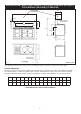
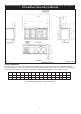


REFER TO FIG 1 & 2
The side wall clearance above the hob shall be greater than 3”.
Surfaces over the top of the range must not be closer than 30” and must not exceed 13” in depth.
The vent slots in the back of the top plate (or shroud) must not be obstructed.
Note: It is essential that the supply cable is routed away from any hot surfaces i.e. hot flue pipes.
In the interests of safety, due consideration must be given to the protection of the electric cable to the Module/Companion.
The AGA TC/DC Integrated Module (Gas Hob) requires a 30 amp power supply and must be connected to the mains with
a cable which complies with the latest edition of the Local and National Wiring Regulations.
Remember that an excess of cable length is required for the possible withdrawal of the range.
A electrical socket type 14-30R must be provided within 5 feet of the left hand side of the range and accessible for
disconnection.
DO NOT position socket above or behind the range.
An easily accessible manual shut off gas valve must be fitted before the metal flexi gas line supply to the range. DO NOT
fit valve behind the range.
Any opening in the wall behind the appliance and in the floor under the appliance must be sealed.
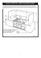
LEVELLING
The AGA TC/DC Integrated Module (Gas Hob) is designed to stand on a flat surface, however any unevenness may be
overcome by packing under the corners of the plinth with a suitable non-combustible material, (up to 1/8”).
LOCATION
5