
Installation Manual


SPECIFICATION - AGA TOTAL CONTROL (TC3) / DUAL CONTROL (DC3) WITH
TC/DC MODULE (GAS HOB) (TC3M/DC3M)
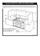
The extension channel section at the rear of each side plate may be removed, if required to clear flue pipes.
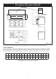
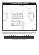
COOKER DIMENSIONS
When surveying for a range cooker installation the actual clearance required for the ‘body’ of the appliance should be
increased overall by
3
/8” (10mm) beyond the figures quoted. This allows safe margin to take into account the natural
dimensional variations found in major castings. In particular the width across an appliance recess could be critical.
C
E
P
E
D
L
Q
B
G
POSITION OF LIDS
WHEN RAISED
OVERHEAD
CUPBOARD
** POSITION FOR GAS SUPPLY PIPE TO MODULE
A B C D E G H J K L M **N **O P Q
mm 1589 948 910 679 75 1330 756 1125 116 3 698 1533 800 760 330
ins 62
9
/16
37
3
/8
35
7
/8
26
3
/4
3 51
3
/4
29
3
/4
44
1
/4
4
1
/2
1
/8
27
1
/2
60
5
/8
31
1
/2
30 13
6
**O
Fig. 1 DESN 517031
**N
A