
Installation Manual

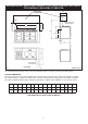


SPECIFICATION - AGA TOTAL CONTROL (TC5) / DUAL CONTROL (DC5) WITH
TC/DC MODULE (GAS HOB) (TC5M/DC5M)
Fig. 2 DESN 517033
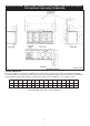
COOKER DIMENSIONS
When surveying for a range cooker installation the actual clearance required for the ‘body’ of the appliance should be
increased overall by
3
/8” (10mm) beyond the figures quoted. This allows safe margin to take into account the natural dimen-
sional variations found in major castings. In particular the width across an appliance recess could be critical.
7
A B C D E F G H J K **N **O P Q R
mm 2084 948 910 679 1330 760 1125 698 116 3 2220 800 3 760 330
ins 82
1
/16
37
3
/8
35
7
/8
26
3
/4
51
3
/4
51
15
/16
44
1
/4
27
1
/2
4
1
/2
1
/8
87
3
/8
31
1
/2
1
/8
30 13
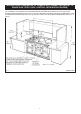
**POSITION FOR GAS SUPPLY PIPE TO MODULE