
Specification Sheets


3
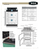
AGA Integrated Dual Fuel Module
Model # TCDC
Installation
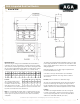
Range Dimensions
When surveying for a range cooker installation the actual clearance
required for the ‘body’ of the appliance should be increased overall by
3/8" (10mm) beyond the figures quoted. This allows safe margin to take
into account the natural dimensional variations found in major castings.
In particular the width across an appliance recess could be critical.
Location
The side wall clearance above
the hob shall be greater than
3". Surfaces over the top of the
range must not be closer than
30" and must not exceed 13" in depth. The vent slots in the back of the
top plate (or shroud) must not be obstructed.
Note: It is essential that the supply cable is routed away from any hot
surfaces i.e. hot flue pipes. In the interests of safety, due consideration
must be given to the protection of the electric cable to the Module/
Companion.
The AGA TC/DC Integrated Dual Fuel Module requires a 30 amp
power supply and must be connected to the mains with a cable
which complies with the latest edition of the Local and National
Wiring Regulations.
Remember that an excess of cable length is required for the
possible withdrawal of the range.
A electrical socket type 14-30R must be provided within
5 feet of the left hand side of the range and accessible for
disconnection.
DO NOT position socket above or behind the range.
An easily accessible manual shut o gas valve must be fitted
before the metal flexi gas line supply to the range. DO NOT
fit valve behind the range. Any opening in the wall behind the
appliance and in the floor under the appliance must be sealed.
Leveling
The AGA TC/DC Integrated Module (Gas Hob) is designed
to stand on a flat surface, however any unevenness may be
overcome by packing under the corners of the plinth with a
suitable non-combustible material, (up to 1/8”).
Specifications are subject to change without notice. Visit www.aga-ranges.com for the most up-to-date information.
A B C D E G H J K L
mm 1589 948 910 679 75 1330 756 1125 116 3
ins 62 ⁄ 37 �/₁₆ 35 ⅞ 26 ¾ 3 51¾ 29¾ 44¼ 4 ½
1
/
M N O P Q
mm 698 1533 800 760 330
ins 27½ 60⅝ 31 ½ 30 13