Wireless/Wired Network IP Camera Night Vision and Remote Operation A622W Wireless PT Camera User Manual www.agasio.com support@agasio.
Thank You for Your Purchase! Agasio IP Cameras are designed and equipped primarily for local and remote purposes such as home or office security surveillance. We provide a variety of products suitable for any type of surveillance system setup, including wired/wireless IP outdoor bullet cameras, IP outdoor dome PTZ cameras, and IP Indoor PT cameras.
Table of Contents 1. 2. 3. 4. 5. 6. 7. 8. 9. 10. 11. 12. 13. 14. 15. 16. 17. 18. 19. 20. 21. 22.
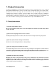
1. Product Introduction The Agasio A622W Wireless Pan/Tilt Outdoor IP Camera features a high quality video sensor combined with a hardened IP66 waterproof enclosure as well as fifty foot night vision range. It also includes an IRCut Filter lens for true color images that are not washed out. The camera supports remote internet viewing, motion detection as well as a built in network video recording system.
(6) Comply with FCC and CE Rules. This device complies with Part 15 of the FCC and CE Rules. Operation is subject to the following two conditions: 1: This device may not cause harmful interference. 2: This device must accept any interference received, including interference that may cause undesired operation. Any changes or modifications not expressly approved by the party responsible for compliance could void the user’s authority to operate the equipment.
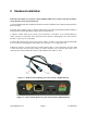
3. Hardware Installation Follow the steps below to set up your camera hardware. Make sure to follow each step carefully to ensure that the camera operates properly. 1. Install the Wi-Fi antenna by twisting the antenna connector clockwise to the camera’s antenna port (for wireless models). 2. Plug the power adapter port into camera’s power supply port. This may be external (outdoor models) or internal (indoor models) depending on which camera you purchased. 3.
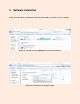
4. Software Installation Firstly, insert the CD into your CD drive, and then open the CD to see the files on your computer. Figure 4.1 – Double-click your CD/DVD Drive to browse the CD files Figure 4.2 – Double Click the “English” folder support@agasio.
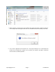
1. Before continuing, we must first run and install the file named “OCX Setup.” Double-click this file, and a dialogue box should appear that reads, “The installation finished successfully!” Press OK. 2. Next, click the application named “Search tool.” The program will begin to run automatically from the CD. If you would like, this software can be copied to your desktop. This will be continued in the next section, “Software Operation.” support@agasio.
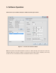
5. Software Operation When Search Tool is double-clicked, the software will show up as follows: Figure 5.1 – Search Tool IP Camera Software Note: The Search Tool IP Camera Software searches for cameras directly connected to the Local Area Network (LAN) of the router the computer is connected to. Please make sure the computer you are using Search Tool on is connected to the same router that the camera is connected to. support@agasio.
There are two different scenarios that may take place: First Scenario No IP Cameras can be found within the Local Area Network (LAN). After about a 1 minute search, the Equipment List will not show any IP addresses or cameras. If this happens we recommend firstly clicking the “Find” button at the bottom of the program to see if any cameras show up. If no cameras show up, try closing the software and re-opening it again to see if any cameras are detected.
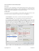
5.2 Configuring Your Network Once your camera’s IP address’ Subnet Mask, Gateway, DNS Server is the same as your PC or router, you need configure the camera’s network parameters manually. IP address: Fill in the IP address assigned and make sure the first three sections of the IP are the same as the IP listed under the “Current Computer” section. For example, in Figure 5.2, the first three sections of the IP that need to be entered under “Equipment Information” where the “IP” field is should be 192.168.1.
6. Viewing Live Video You can access the camera using Search Tool, IP Camera Tool or IE, Firefox, Safari, Google Chrome or other standard browser directly. 1. In Search Tool, there is a field that reads “Inner access.” This lists the current Local IP Address of the camera. This IP address can be entered in any browser’s URL field to bring up the camera login. You can also push the button on the right of the field that reads “Open.” This will open the camera up in your default browser. Figure 5.
Figure 5.5 – Login is required (Default username is admin with no password) Figure 5.6 – You can choose which option to sign in as depending on your browser support@agasio.
There are a few different options to choose from when signing in. The three primary options are: (1) “Active Mode” (For IE Browser): available for Internet Explorer 6.0 and above. (2) “Server Push Mode”: available for Firefox, Safari, and Google Chrome browsers. (3) “Snap Motion Mode”: available within mobile phone browsers. 7. Viewing with Internet Explorer Choose “Active Mode” (For IE Browser), and sign in.
If there is still no live video after confirming the ActiveX add-on module or if you continue to get a black screen with the red “X” at the top left, you will need to try and enable the ActiveX options of Internet Explorer’s security settings using the following steps: Note: You may need to disable your firewall firstly to see if this is not causing the issue.
This will take you to the Advanced Settings where you can manually change the ActiveX control options. Scroll down on this screen to where it reads “ActiveX controls and plug-ins” as the parent option, and set the child options to “Enable.” The most important options to keep enabled are the following: Enable: “Download unsigned ActiveX controls” Enable: “Initialize and script ActiveX controls not marked as safe” Enable: “Run ActiveX controls and plug-ins” support@agasio.
One more setting that will need to be changed is located under the “Advanced” tab in the “Internet Options” window. Once on the “Advanced” tab, scroll down to find the parent category named “Security.” Check the option which states “Allow software to run or install even if the signature is invalid.” This is pictured below: Note: Make sure that your firewall or anti-virus software is not blocking the camera software or ActiveX.
8. Viewing with Chrome, Firefox, Safari When at the log-in screen, choose “Server Push Mode” (For Safari, Firefox, Chrome), and click “sign in.” Server Push Mode does not support ActiveX, so some functions are not available when using these browsers, such as Play, Stop, Record, Audio, Talk, and Snapshot. If you want to use these functions, please use IE Browser. Note: There is an extension for Chrome and Firefox that allows you to open an Internet Explorer tab within the respective browsers.
9. Main Menu Interface Here is a quick overview of the options available on the home screen of the Agasio camera. This navigational circle controls the camera pan and tilt. You can click the arrows around the circle to pan and tilt accordingly. The Pan/Tilt feature will only work if a camera has this function available. Clicking this button will make the camera go on a vertical cruise. The camera will tilt to its maximum height and tilt back down to its lowest angle. support@agasio.
Clicking this button will make the camera go on a horizontal cruise. The camera will pan as far as possible to the left and then as far as possible to the right. Clicking this button will flip the image vertically, usually used when a camera is mounted upside-down. Clicking this button will flip the image horizontally, usually used when a camera is mounted upside-down. This button is used for turning on the IR night vision lights. This button is used for turning off the IR night vision lights.
This setting changes the image resolution. This setting changes the image frequency. This setting changes the image brightness. This setting changes the image contrast. This button resets all main menu options to factory default. Clicking this button will start a manual recording which will record to the folder you have specified. To change where videos are saved, hover over “Path Settings,” and click “Record Path.
10. Administrative Settings When logging in as an Administrator, you have the ability to alter or change options other users cannot change. Administrator privileges allow access to all of the settings and operations of the camera; you can set and control it freely. Some of the special options solely for administrators are listed below: Alias Settings: You can name the IP camera to any name you see fit. To find this option, hover over “Device Settings,” and click “Alias Settings.
11. Multi-Device Settings Multi-Device settings allow you to view up to 9 cameras simultaneously on one screen. If you have multiple cameras set up, even if they are not on the same network, they can all be viewed when set up correctly in Multi-Device Settings. To navigate to the Multi-Device Settings page, hover over “Device Settings,” and click on “Multi-Device Settings.” On the configuration page, you will be able to see all the cameras currently connected to your Local Area Network (LAN).
Figure 11.1 – More fields drop down when you want to add another camera Click the camera that you would like to add from the list, and the fields should automatically populate with the IP address, Alias, and HTTP port. Enter the username and password for that camera, and click “Add.” You can repeat this process for up to 9 cameras. If a camera is not located on the LAN, you can simply input its external IP address, port, username and password, and click “Add.” Don’t forget to click “Submit” when finished.
To view the cameras in a multiple setup view, click on “Live Video” on the left side of the interface. You can then change the view from single, to 4-view or 9-view depending on how many cameras you have added. This option is seen pictured below. Figure 11.2 – An example of using 4 cameras simultaneously on the same screen support@agasio.
12. Basic Network Settings Figure 12.1 – The Basic Network Settings page This section of the camera contains the basic network LAN settings; these are the same settings that are seen in the Search Tool software. If you need to change the IP address in the future for any reason, you can do so from here as an alternative rather than using the Search Tool. This section has an extra field named “Obtain IP from DHCP Server.” This option allows an IP address to be automatically assigned to the camera.
Firstly, make sure your router is wireless capable. You will not be able to use wireless without a wireless router. Make sure the Wi-Fi antenna is properly installed to the back of your camera. Twist the connector onto the camera’s Wi-Fi port so it is connected tightly. Login to the camera and sign in to get to the main camera screen with live video. To get to the Wireless Settings page, hover over “Network Settings,” and click on the option that reads “Wireless LAN Settings.
Encryption – This field describes the type of encryption your network is running. This is different for all routers. The most popular encryptions are WEP, WPA, and WPA2. You can find this information by going to the Control Panel on your computer and navigating to “Network and Internet.” Figure 13.2 – Navigate to Manage Wireless Networks, right click on your network, click Properties support@agasio.
Figure 13.3 – In Properties, click the Security tab at the top, you will then see your Wireless Network’s Encryption information and security key. After navigating to the window in Figure 13.3, you can use the listed information to manually input into the Wireless LAN Settings page. In this window, “Security Type” and “Encryption Type” will be the two factors you will need to use to determine the value of the Encryption field in the Wireless Settings Page. In the example in Figure 13.
Using the following information above, we should have our Wireless Settings page look like the following. Figure 13.4 – All fields have been filled in with the information found from our wireless network The last step would be to click “Submit.” Once this happens, the camera will take 30 seconds to reboot. It will go through the same pan/tilt cycle (if it is a pan/tilt camera) just as it does when it is powered up. This indicates the wireless settings being uploaded to the camera.
14. ADSL Settings When your camera is directly connected to the Internet via ADSL, you may need to enter your Internet Service Providers information. You can enter your ADSL Username and Password within the ADSL Settings in the camera. You can find this setting by hovering over “Network Settings,” then clicking on “ADSL Settings.” To see all fields, remember to check the box that reads “using ADSL Dialup.” Once finished, remember to click “Submit.” 15.
15.1 Linksys Routers To begin, open a web browser and type “192.168.1.1” in the address bar and press Enter on your keyboard. You will be prompted to log in. Log in with a username of “admin” and password of “admin” or leave it blank. These are default values; if these do not work consult the router’s user manual. If you have changed the username and password, please use those values instead. Then click OK.
Next, under the custom fields on the left side of the screen, insert the name you would like to call the camera (IPCAM). Then, under the categories “External Port” and “Internal Port,” type your port number, in our case we would type port “99.” The protocol should stay on “Both.” In the field under the category “To IP Address,” type in the fourth part of the IP address of the camera (which starts with 192 etc.). Don’t forget to check the box which is under the category “Enabled.
Figure 15.4 – An example of an external IP address. Use this along with your port number to access the camera remotely on any browser or smartphone. For example, we would type in our browser the following: “50.79.253.205:99” and push Enter. This should take us to our camera. Remember to always add a colon and the port number after the external IP address. 15.2 Belkin Routers To begin, open a web browser and type "192.168.2.1" in the address bar and press Enter on your keyboard. 1.
2. Belkin routers do not ship with a password. If you have not set up a password to the router, just click on Submit. Otherwise, type in your password and then click Submit. 3. Click on "Virtual Servers" under the Firewall category in the menu on the left side of your screen. 4. Enter the following information: Check the box under the category that reads “Enabled.” Type a general description of the application; in this case it will be an Agasio Camera, so type IPCAM.
Under the “Private Port” category, simply put the port 99 again (your port may be different). Click on the “Apply Changes” button to save the changes. Figure 15.2 – An example of what the port forwarding should look like within a Belkin router After this is done your camera should be set up to be remotely viewed! You can double check if your port is forwarded by going to http://www.canyouseeme.org and typing in your port and checking that way.
15.3 D-Link Routers To begin, open a web browser and type “192.168.0.1” in the address bar and press Enter on your keyboard. You will be prompted to log in. Log in with a username of “admin” and password of “admin” or leave it blank. These are default values; if these do not work consult the router’s user manual. If you have changed the username and password, please use those values instead. Then click OK. Figure 15.
To see if you can access your camera with the external IP address, find out your external IP address by going to http://whatismyipaddress.com. The IP address there is your external IP address, which you will use in your URL bar along with the port number to access the camera from any browser or on your smart phone using 3G or 4G. Figure 15.4 – An example of an external IP address. Use this along with your port number to access the camera remotely on any browser or smartphone.
Figure 16.1 – An example of the DDNS Service Settings page configured to DynDNS.org There is a free trial for Dynamic DNS Service available from Dyn.com (DynDNS.com). Below are the steps to sign up for a free account and use one free host name. Enter the following URL into your browser: http://dyn.com/dns/dyndns-pro-free-trial/. You will see the following image near the top of the page, click “Start the Trial” to begin. support@agasio.
Figure 16.2 – Choose your hostname and fill in the IP address field with the external IP address provided by DynDNS.com in the blue hyperlink. You will be asked to add a new hostname. You can type a custom name for the hostname and use any type of ending for the last part of the URL. In this case, we used “dyndns.org,” and used “Agasio” as our custom hostnames. Keep the service type as default, “Host with IP Address.” In the field that reads “IP Address, Dyn.
Figure 16.3 – Setup your trial account username and password, along with your e-mail address Enter a Username and Password you would like to use with your Dyn.com account. In this example we used the username “Agasio” and password “Agasio.” Enter your e-mail address and type in the numbering on the security image. Make sure to check the box which reads “I accept the terms of Dyn’s Acceptable Use Policy etc.” and click “Create Account.” support@agasio.
After clicking “Create Account,” you will see the following screen. An e-mail will be sent to the e-mail address you provided. Check your e-mail to find the e-mail from Dyn.com asking you to confirm your account. Click on the link listed in the e-mail and it will take you back to the next steps on creating your account. Figure 16.4 – Confirm validation of your trial account by clicking the verification link found in your e-mail support@agasio.
Figure 16.5 – Insert your credit card information to continue creating your trial account, you will not be charged by Dyn.com for any services unless you fail to cancel your trial within 14 days. A valid credit card is needed for your DynDNS trial; you may cancel this trial any time after creation within 14 days to keep one free host name, which is all you need for an unlimited number of cameras. Once your account has processed and confirmed, you will see the following screens confirming your host names.
Figure 16.6 – The screens above indicate the completion of your trial account setup, note that you can always cancel your trial and keep one hostname free, without a charge. support@agasio.
Figure 16.7 – As seen above, cancelling your trial has no effect on the first host name you register, thus allowing you to use this host name for free for your cameras. support@agasio.
You have now successfully obtained a DDNS address which you can use within the camera. See Figure 16.8 for additional reference on how to set up the DDNS hostname you have created to work with the camera. Figure 16.8 – The username and password in the account we created is entered here, along with the hostname we registered. All that needs to be done is to push “Submit.
Note: If you have a dynamic IP address, make sure you have downloaded DynDNS’s “Update Client” and installed it onto your computer. The update client automatically updates your IP address as it changes so that the hostname will always be updated with the external IP address, even if it changes. You can locate the download page at www.dyn.com/support/clients/. Figure 16.9 – DynDNS update client download page support@agasio.
17. E-mail and FTP Settings Figure 17.1 – The Mail Service Settings Page Seen in Figure 17.1 is the Alarm E-mail Notification Settings. Configuring this page will allow you to receive e-mail alerts when motion is detected to your e-mail, you will also receive pictures of the motion detection to your e-mail address if you choose to do so. The fields listed are detailed as follows. Sender – This should be your e-mail address, for example, Agasio@gmail.com.
Transport Layer Security Protocol – This protocol differs between e-mail providers, check with your provider to see if you should use TLS, STARTTLS, or None. Need Authentication – Usually you will need to have this checked, once you check it, two new fields will drop down that read “SMTP User” and “SMTP Password,” you would put in your e-mail account username and password in these fields. For example, we would put “Agasio” (without the @gmail.
18. Alarm Settings Figure 18.1 – An example of the Alarm Settings page along with the enabled scheduler As shown above, there are two different modes for alarm settings. The first mode is motion detection, which can be seen above. The sensitivity of motion detection can be adjusted easily according to your requirements. If you need higher sensitivity for the alarm settings, the number should be lower. We recommend placing the number on “5.
19. Hard Reset and Firmware Upgrades If for any reason your camera stops functioning or is giving you errors, you can always “hard reset” the camera. This will completely wipe the camera settings that have been set, including any wireless settings, FTP settings, or Alarm Settings. The hard reset allows you to set the camera back to default factory settings when you are not able to access the camera anymore. Figure 19.
Figure 19.2 – The Upgrade Device Firmware page This section is for upgrading your camera’s firmware and Web UI. The firmware and WebUI should be available from our support page at www.agasio.com for your specific camera. Please be aware that upgrading your firmware or WebUI could result in some features of your camera not working correctly if you update the wrong version. If you are unsure of which firmware or WebUI to upgrade, don’t hesitate to contact us at support@agasio.com.
21. Rebooting Your Camera To reboot your camera within the camera itself, you can do so by hovering over “Device Settings,” and clicking the button which reads “Reboot Device.” Once you click this button, a window similar to Figure 21.1 will appear, click OK to confirm and wait about one minute for the camera to reboot. The camera should appear again within one minute of rebooting. Figure 21.1 – Confirmation window asking to confirm a camera reboot support@agasio.
22. Warranty Information 1. Most products can be returned for either a refund or for a replacement of the same item. Refunds are subject to a 15% restocking fee and must be requested within 14 days of receiving the item. An item is not eligible for return after these 14 days. The restocking fee is ultimately deducted from the refund amount. We charge this 15% restocking fee for all returns to encourage customers to purchase products they intend to keep.