DRYSTAR AXYS 3 Do one of the following: •Press the Confirm key (YES) to start the QC procedure and proceed with step 4. •Press the Escape key (NO) to quit. 4 Define the tray for printing. The ‘Select tray’ screen appears: 1.Upper tray 2.Lower tray Note: When controlling the Drystar AXYS via a remote PC, The ‘Select input tray’ screen is preceded by a screen, which allows you to: Note: Start the quality control procedure immediately, Note: Edit additional data for the last quality control measuring.
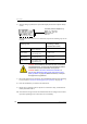
DRYSTAR AXYS 6 After the image is printed, the system will display all measured optical density values: DD: 1.56 (Densitometer=MB924) The density levels are displayed, e.g: Max D: x.x Hi D: 2.23 Mid D: 1.13 Lo D: 0.4 Base+Fog: 0.20 DD: x.xx The displayed values (that have to be monitored) represent the following steps on the test film: Value (Macbeth units) (according to NEMA standards XR 23-2006) Operating Level Base + Fog the density value of the Base + Fog step 0. 22 ± 0.
DRYSTAR AXYS 11 Record the respective aim (average) values as the ‘Operating levels’ on Charts 2A and 2B (‘Drystar AXYS Daily Density Control Chart’). Refer to “Charts for mammography QC (optional)” on page 155. The calculated ‘Operating levels’ should be as follows: Operating Level Value (Macbeth units) (according to NEMA standards XR 23-2006) Base + Fog 0. 22 ± 0.03 Low density 0.45 ± 0.07 Mid density 1.20 ± 0.15 High density 2.20 ± 0.15 12 These charts will be used for the daily quality test.
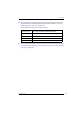
DRYSTAR AXYS Establishing the image geometry reference values for mammography application (DT 2 Mammo) (optional) Procedure 1 Print the QC mammography test image or use the previously printed test image. For an example, see “QC test image for mammography applications (DT 2 Mammo) (optional)” on page 107. 2 To determine the reference values for geometry, measure the distances A and B of the geometric square on the test image.
DRYSTAR AXYS Verifying Acceptable Spatial Resolution and Artifact Levels and Low Contrast Visibility for mammography application (DT 2 Mammo) (optional) WARNING: Good viewing conditions are important for the correct interpretation of both diagnostic and test images. Make sure that the light box intensity (luminance) is between 3000 and 6000 cd/ m² (4500 and 6500 °K) for mammography. Use a magnifying glass and use shutters to collimate. Make sure the ambient light is low.
DRYSTAR AXYS 6 These charts will be used for the weekly quality test. For more information, refer to “Performing the Weekly QC tests for mammography application (DT 2 Mammo) (optional)” on page 118. WARNING: In case of significant artifacts or insufficient spatial resolution, the cause must be found and the problem solved before any further clinical films can be printed.
DRYSTAR AXYS Performing quality control (QC) tests for mammography application (DT 2 Mammo) (optional) The following procedures must be performed daily, weekly or annually as indicated. The reason for performing quality control tests is to determine if any significant image quality variation or deterioration has occurred which may require corrective action. Comparing the results of the tests with the reference values previously established does this.
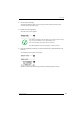
DRYSTAR AXYS Performing the daily QC test for mammography application (DT 2 Mammo) (optional) WARNING: This test must be performed every day before any clinical film can be processed. Procedure 1 Turn on the Drystar AXYS and wait at least for 15 minutes. Refer to “Switching on the Drystar AXYS” on page 48. 2 Press the Key-operator key to enter the Key-operator mode. 3 Press the down key seven times, followed by the ok key to select ‘QC’. 5 6 7 8 9 Restore config.
DRYSTAR AXYS 6 Press the Up/Down arrow keys to select the desired tray, followed by the Confirm key. The following screens appear successively: The Drystar AXYS will automatically print the QC test image. After the image is printed, the system will display all measured optical density values: DD: 1.56 (Densitometer=MB924) The density levels are displayed, e.g: Max D: x.x Hi D: 2.23 Mid D: 1.13 Lo D: 0.4 Base+Fog: 0.20 DD: x.
DRYSTAR AXYS Performing the Weekly QC tests for mammography application (DT 2 Mammo) (optional) Spatial Resolution, Artifact Test and Low Contrast Visibility To identify artifacts and verify spatial resolution you must perform the following test weekly or as needed for troubleshooting image quality problems. WARNING: Good viewing conditions are important for the correct interpretation of both diagnostic and test images.
DRYSTAR AXYS 5 Record these values on Chart 3 (‘Drystar AXYS Artifacts and Spatial Resolution Control Chart’). Refer to “Charts for mammography QC (optional)” on page 155. WARNING: In case of significant artifacts, insufficient spatial resolution or failure of any other recommended QC tests, the cause of the problem must be identified, and corrective action must be taken before the Drystar AXYS can be used for any further clinical imaging.
DRYSTAR AXYS Performing the Annual QC tests for mammography application (DT 2 Mammo) (optional) Geometric Consistency Test To be able to notice fluctuations in image size and aspect ratio, you must perform this procedure once a year. Procedure 1 First, perform the daily test. 2 Measure the distances A and B of the geometric square on the QC mammography test image. Refer to “Establishing the image geometry reference values for mammography application (DT 2 Mammo) (optional)” on page 112.
DRYSTAR AXYS Preventive maintenance schedule The Drystar AXYS is designed for trouble-free operation. Maintenance and cleaning involve only some minor user tasks. Refer to the following pages for the appropriate cleaning procedure. Interval What to do? Ad hoc “Cleaning the exterior” on page 122 When image quality tends to degrade. An appropriate warning message is displayed.
DRYSTAR AXYS Cleaning the exterior Procedure 1 Switch off the Drystar AXYS by following the procedure as described in “Switching off the Drystar AXYS” on page 63 2 Remove the power plug from the socket. 3 Wipe the exterior of the printer with a clean, soft, damp cloth. Use a mild soap or detergent if required but never use an ammonia–based cleaner. Be careful not to get any liquid in the power cord port.
DRYSTAR AXYS Cleaning the print head WARNING: Print head cleaning must be done when image quality problems occur. Procedure 1 Press the Key-operator key to enter the key-operator mode. 2 On the key-operator main menu, press the Down key five times, followed by the Confirm key to select ‘Calibration’. 5 6 7 8 9 Restore config. Calibration Service Actions Quality Control Installation 3 On the Select calibration menu, press the Down key, followed by the Confirm key to select ‘Clean therm. head’.
DRYSTAR AXYS 124 5 Open the top cover. 6 As soon as the top cover is opened, the ‘Thermal head cleaning’ screen continues giving the following instructions: 7 Open the hold-down bracket.
DRYSTAR AXYS 8 Open the print head unit. WARNING: The print head unit can be warm. 9 Locate and check on sight the print head resistor line. Note: Be careful not to touch the print head resistor line with your fingers.
DRYSTAR AXYS 10 Clean the print head resistor line. Gently pass over the resistor line a few times with a lint free cloth, slightly moistened with Isopropyl alcohol or Ethanol. Do this only in one direction, i.e. from left to right, without lifting the cloth. Note: Do not apply any pressure on the print head because this pressure may cause damage on the interconnections underneath the print head. 11 Close the print head unit, the hold-down bracket and finally the top cover.
DRYSTAR AXYS Troubleshooting checklist The table below lists some general problems, which can occur when working with the Drystar AXYS. Q The Drystar AXYS does not print.
DRYSTAR AXYS Q The quality of the printed images is bad (printing remains possible).
DRYSTAR AXYS Clearing of film jams A film jam can be situated either: Q In the input tray section. Refer to “Film input tray jams” on page 130 . Q In the top section. Refer to “Film transport jams (clearing from the top)” on page 133 . Jams can be caused by: Q Opening the top cover or input tray while a film is actually being printed. Refer to “Unauthorized opening of the printer” on page 136 . Q Loading films incorrectly. Refer to “Film identification problems” on page 137 .
DRYSTAR AXYS Film input tray jams A film jam in the input tray can occur when the Drystar AXYS is opened while a film is currently printed, or when an individual film is incorrectly inserted in the input tray. Refer also to “Film identification problems” on page 137 . The following screen indicates that a jam occurred in the input tray. To remove a jammed film in the input tray: 1 Open the film input tray. If a film is jammed, gently remove the sheet.
DRYSTAR AXYS 2 To get a clear view, it may be necessary to remove any remaining film sheets, including the protective (white) sheet. 3 Check if the film feed section of the input tray is clear. Reposition the film stack in the film tray, making sure that all the sheets are kept correctly in place (refer to “Loading films” on page 76).
DRYSTAR AXYS 4 132 Close the film input tray.
DRYSTAR AXYS Film transport jams (clearing from the top) The following screen indicates that a jam occurred in the upper section of the film transport system. Blinking Note: Please note that instructions for removing a film jam in the transport section are present on a sticker at the inside of the top cover. To remove a jammed film in the transport system: 1 Open the top cover.
DRYSTAR AXYS 2 Open the hold-down bracket. 3 Open the print head unit. WARNING: The print head unit can be warm.
DRYSTAR AXYS 4 Gently remove the film sheet(s). Note: Never use force to clear the jammed film. If it is not possible to gently remove the jammed film by pressing the transport buttons, proceed with the procedure as follows. Note: Verify that no film sheets remain in the print head compartment. 5 If the film jam has been cleared, close the printer. You can resume work. WARNING: Never reuse a jammed film. This may cause damage to the thermal head and/or dust problems.
DRYSTAR AXYS Unauthorized opening of the printer A jam can be caused by opening the printer covers or one of the input trays while a film is actually being printed. The following screen indicates that a jam has occurred: printing. Next time wait until printer is in "Ready" condition. 1 Remove the jammed sheet. Refer to “Clearing of film jams” on page 129 . 2 Press the Confirm key to continue.
DRYSTAR AXYS Film identification problems When you load a new film pack, the new Film Identification tag is read and the tray film format and type are set based upon the info in the Film Identification tag (RF-tag). This tag is only readable when the film pack is inserted in the correct way.
DRYSTAR AXYS No identification code detected This error message appears when the Film Identification tag is not readable. There are two possible solutions for this problem: Q Reload the current film pack or load another film pack Q Overrule the Film Identification tag of the film pack To reload the current or another film pack 1 In case the Drystar AXYS does not start printing after re-inserting a film pack, first check if this film pack is inserted correctly.
DRYSTAR AXYS To overrule the Film Identification tag of the film pack If the “Overrule RF-tag Reading” setting is active, you can overrule the Film Identification tag setting of the current film pack. In this case you can continue printing using a limited Maximum Density.
DRYSTAR AXYS 3 Press the Confirm button. •If the “Overrule RF-tag Reading” Setting is active, the following message is displayed: OVERRULE IDENTIFICATION CODE IS ACTIVE Dmax is limited due to safety reasons •If the “Overrule RF-tag Reading” Setting is not activated, the following message will be displayed: Re-enable printing by inserting correct film media pack.
DRYSTAR AXYS Invalid content of Film Identification tag When you insert a new film pack with invalid content in the Film Identification tag, the following message is displayed: Try loading another film pack, or call your local service organization to resolve this problem. Film overrun from current pack The following message is presented when more than 110 copies are printed from the current film pack: THIS PACK. please insert other film pack. Reload a new film pack to resolve this problem.
DRYSTAR AXYS 142 2852 A EN 20070205
A Equipment information sheet This appendix covers the following sections: ❑ Specifications ❑ Viewing the system info area on a film
DRYSTAR AXYS Specifications Product description Type of product Printer Commercial name Drystar AXYS Original seller/manufacturer Agfa-Gevaert N.V. Labelling TÜV-, cULus-Certification Mark, CE-marking CCC Mark Dimensions Dimensions (approx. values in cm) Weight Unpacked: width 72.8, length 71.5, height 67.6 Packed: width 89, length 100, height 80 Unpacked: approx. 90 kg Packed: approx.
DRYSTAR AXYS Network connectivity Ethernet / connectors RJ45 twisted pair for 10/100Base-TX; Serial RS232 connection Network protocols (TCP/IP services) FTP, Telnet, HTTP DICOM (Default) Image formats TIFF Postscript Not available Power consumption - heat dissipation During operation 250 W - 900 kJ/h In stand-by 70 W - 252 kJ/h Peak power (absolute max.
DRYSTAR AXYS Environmental transport conditions Note: Climate conditions for transport are in accordance with EN60721-3-2-class 2K4. Temperature Between -40°C and 70°C (transport) Relative humidity not combined with rapid temperature changes 95% at +45°C Noise emission (method of measurement in accordance with DIN 45635 part 19) During operation Max. 64 dBA In stand-by Max. 54 dBA Total acoustic A-weighted noise power During operation 62 dB ( = 6.4Bel = 6.4B) In stand-by 53 dB ( = 5.3Bel = 5.
DRYSTAR AXYS Imaging Array - Diagnostic area - General radiography 10” dimensions 10x12” 12” dimensions pixels mm pixels mm 4880 244 5860 293 11” dimensions 11x14” 14” dimensions pixels mm pixels mm 5376 268,8 6922 346,1 14” dimensions 14x14” 14” dimensions pixels mm pixels mm 6882 344,1 6882 344,1 14” dimensions 14x17” 17” dimensions pixels mm pixels mm 6922 346,1 8368 418,4 Imaging Array - Diagnostic area - Mammography (optional) 8” dimensions 8x10” 10” dimen
DRYSTAR AXYS Viewing the system info area on a film On the top right corner of each film, a “System info” area will be printed. This info can only be read using a magnifying glass. Film Black border Diagnostic area Clear border Transport direction System info area The System info area contains info about: Q Printer: (serial number, densitometer info, film counts, software version, etc.), Q Controller (image source, date, time, etc.).
B Quality Control Charts This appendix covers the following topics: ❑ Charts for general radiography QC ❑ Charts for mammography QC (optional)
DRYSTAR AXYS Charts for general radiography QC Quality Control for Chart 1 General radiography applications Drystar AXYS : Determination of Operating Levels Imager Type: __________ Serial #: _________________ Date ____________________ Film Type: ____________ Emulsion #: ______________ Input Tray ________________ Densitometer: _________________ (default selection) Step 1: Print QC Test images on five consecutive days. Record the optical densities measurements in the tables below.
DRYSTAR AXYS Quality Control for Chart 2A General radiography applications Drystar AXYS Daily Density Control Chart Imager Type: __________ Serial #: _____________ Film Type:____________ Emul #:____________ Densitometer: ____________________ (default selection) Input Tray:_________ Da te : Initia ls: Upper Control limit = +0.05 Calculated Reference Low Density Level Lower Control Limit = -0.05 Low Density Upper Control limit = +0.
DRYSTAR AXYS Quality Control for Chart 2B General radiography applications Drystar AXYS Daily Density Control Chart Imager Type: __________ Serial #: _____________ Film Type:____________ Emul #:____________ Densitometer: ____________________ (default selection) Input Tray:_________ High Density Upper Control limit = +0.20 Calculated Reference High Density Level Lower Control Limit = -0.
DRYSTAR AXYS Quality Control for Chart 3 General radiography applications Drystar AXYS Artifacts and Spatial Resolution Control Chart Test Frequency: Weekly Input Tray: ____________ Drystar AXYS Serial # _____________ Initial Reference Test Date Initial Reference Artifacts Initial Reference Dot Visibility Initial Reference Low Contrast Month Day Artifacts Visibility of all Dots Low Contrast Visibility Month Day Artifacts Visibility of all Dots Low Contrast Visibility Month Day Artifacts Visibility of a
DRYSTAR AXYS Quality Control for Chart 4 General radiography applications Drystar AXYS Geometric Consistency Control Chart Test Frequency: Annually or as required Input Tray: _______________________ Reference Dimensions Date: Measured Dimensions Date: A: Consistency Aspect Ratio A/Aref A/B Bref B: B/Bref Reference Dimensions Date: Measured Dimensions Date: A: Consistency Aspect Ratio A/Aref A/B B: B/Bref Aref Aref Bref 154 Drystar AXYS Serial # _____________ 2852 A EN 20070205
DRYSTAR AXYS Charts for mammography QC (optional) Quality Control for Chart 1 Mammography applications Drystar AXYS : Determination of Operating Levels Imager Type: __________ Serial #: _________________ Date ____________________ Film Type: ____________ Emulsion #: ______________ Input Tray: _______________ Densitometer: _________________ (default selection) Step 1: Print QC Test images on five consecutive days. Record the optical densities measurements in the tables below.
DRYSTAR AXYS Quality Control for Chart 2A Mammography applications Drystar AXYS Daily Density Control Chart Imager Type: __________ Serial #: _____________ Film Type:____________ Emul #:___________ Densitometer: _________________ (default selection) Input Tray: ________ Date: Initials: Upper Control limit = +0.03 Calculated Reference Base + Fog Level Base + Fog Lower Control limit = -0.03 Date: Initials: Upper Control limit = +0.
DRYSTAR AXYS Quality Control for Chart 2B Mammography applications Drystar AXYS Daily Density Control Chart Imager Type: __________ Serial #: _____________ Film Type:____________ Emul #:___________ Densitometer: _________________ (default selection) Input Tray: ________ Date: Initials: Mid Density Upper Control limit = +0.15 Calculated Reference Mid Density Level Lower Control limit = -0.15 High Density Upper Control limit = +0.
DRYSTAR AXYS Quality Control for Chart 3 Mammography applications Drystar AXYS Artifacts and Spatial Resolution Control Chart Test Frequency: Weekly Input Tray: ____________ Drystar AXYS Serial # _____________ Initial Reference Test Date Initial Reference Artifacts Initial Reference Dot Visibility Initial Reference Low Contrast Month Day Artifacts Visibility of all Dots Low Contrast Visibility Month Day Artifacts Visibility of all Dots Low Contrast Visibility Month Day Artifacts Visibility of all Dots
DRYSTAR AXYS Quality Control for Chart 4 Mammography applications Drystar AXYS Geometric Consistency Control Chart Test Frequency: Annually or as required Drystar AXYS Serial # ____________ Input Tray: ______________________ Reference Dimensions Date: Aref Measured Dimensions Date: A: Consistency Aspect Ratio A/Aref A/B Bref B: B/Bref Reference Dimensions Date: Measured Dimensions Date: A: Consistency Aspect Ratio A/Aref A/B Aref Bref 2852 A EN 20070205 B: B/Bref 159
DRYSTAR AXYS 160 2852 A EN 20070205
DRYSTAR AXYS 2852 A EN 20070205 161
Printed in Belgium Published by Agfa-Gevaert N.V.