
User Manual Part 1


37
2852 A EN 20070205
DRYSTAR AXYS
Always take into account the markings provided on the inside and outside of
the printer. A brief overview of these markings and their meaning is given
below.
Symbol Explanation
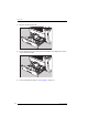
Figure 14: Caution hot:
Keep hands clear from the thermal print head.
Figure 15: High voltage
In order to reduce the risk of electric shock, do not
remove any covers.
Figure 16: Type B
equipment:
Indicates that the Drystar AXYS complies with the lim-
its for type B equipment.
Figure 17: Supplementa
ry protective earth
connector:
Provides a connection between the Drystar AXYS and
the potential equalization bus bar of the electrical sys-
tem as found in medical environments. This plug
should never be unplugged before the power is turned
off and the power plug has been removed.
Figure 18: Intergroundi
ng connector:
Provides a connection between the printer and other
equipment, which might exhibit minor ground poten-
tial differences. These differences may degrade the
quality of communication between different equip-
ment. Never remove connections to this terminal.
Figure 19: Protective
earth (ground):
Provides a connection between the printer and the
protective earth of the mains. Do not remove this con-
nection, because this will have a negative influence on
the leakage current.
Figure 20: Power button
Note that the power cord has to be disconnected from
the wall outlet in order to disconnect the unit entirely
from the mains.