:ANAPURNA L/XL OPERATOR MANUAL Version 1.
:ANAPURNA L/XL OPERATOR MANUAL TABLE OF CONTENTS 1. Safety Instructions ..................................................................................................................................................................... 3 2. Printer Overview and Features................................................................................................................................................. 4 2.1 Front view, parts & locations ........................................................
:ANAPURNA L/XL OPERATOR MANUAL 1. Safety Instructions. IMPORTANT Be sure to follow all instructions and warnings in this manual when using the equipment. WARNING Do NOT look directly into the UV light when printing, and don’t expose your skin directly to the UV light. If you need to look at the direction of the light, wear protective glasses or look through the front cover glas. WARNING UV ink contains chemicals, when handling the ink, wear protective gloves to protect your skin, and protective glasses.
:ANAPURNA L/XL OPERATOR MANUAL 2. Printer Overview and Features. System Dimensions: ANAPURNA XL Max. media width: 2.5m (printable width: 2.48m) ANAPURNA L Max. media width: 1.6m (printable width: 1.
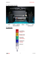
:ANAPURNA L/XL OPERATOR MANUAL 2.1. Front view, parts & locations 2.2.
:ANAPURNA L/XL OPERATOR MANUAL COVER “OPEN” SENSOR This engine is equipped with a “safety sensor” on the Front and Rear cover. Carrige movement and printing can only be done with covers closed. . 1. When carriage is waiting: (Purge or Home) When a cover is “open”, you will see the “door open error” on the screen, and the carriage will not move to Home or Purge if requested. 2.
:ANAPURNA L/XL OPERATOR MANUAL 2.3. Head Carriage view, parts 2.4.
:ANAPURNA L/XL OPERATOR MANUAL 3. Head technology. - Spectra Nova 256/80 AAA JA (Jetting Assembly) • • • • Calibrated Drop Size: 75 pl 256 addressable jetting nozzles, single line Nozzle spacing: 279 microns (0,011”) Intrinsic resolution: 91 dpi - 8 JA mounted in head base plate • 7 heads in line • 1 head mounted in front of the other heads, used for “Pre-White”.
:ANAPURNA L/XL OPERATOR MANUAL 4. :Anapurna UV Curable Ink. 4.1. General information - The :Anapurna UV curable ink is specially developed for best performance on the :Anapurna engine. - Sharp printing, vibrant colors on a wide range of media - Ensures dry and instant ready prints with excellent outdoor durability - Use of light inks • Enhance apparent output resolution by using Light Cyan and Light Magenta • Results in smooth highlights - Ink usage: ± 10ml/m², all colors together (6) 4.2.
:ANAPURNA L/XL OPERATOR MANUAL 5. Ink Circuit. 5.1. Main ink tanks - The main ink tanks are located on the right side of the engine. - 1.6 liter per color - Low level detection at 0.3l. (± 4h to print) Audible & visual alarm on the Signal tower. - Ink can be refilled in while printing - White ink tank has a continuous working stirring rod inside. - Tanks: WARNING ONLY refill with the 1liter bottle, when the low level alarm goes off.
:ANAPURNA L/XL OPERATOR MANUAL - Read out: - How to make changes: At this stage, you also need to Press the “AT” button, to close the procedure.
:ANAPURNA L/XL OPERATOR MANUAL 5.4. The 2-Way valves - Normal printing: - The color valves are positioned in the “I” direction. The ink can flow to the head. - Purging the heads: - In case of clogged nozzles, or misfiring nozzles; Push the “Purge” button at very short intervals, this will cause ink flowing through the heads, this will un-clog the missing nozzles.
:ANAPURNA L/XL OPERATOR MANUAL 5.5. Printing heads - Ink supply by means of negative pressure: By means of negative pressure, the ink is kept in the print heads. A too high setting will cause missing nozzles, or no ink firing at all. When the pressure is too low, the ink will leak out of the heads. The Neg. Pressure should be set to -.0.34 The system will adjust the setting, when the temperature on the Head Base plate is getting too high.
:ANAPURNA L/XL OPERATOR MANUAL - Head base temperature control: Read-out on display: - The upper value on the display, is the actual temperature, the lower value is only an indication. The actual temperature will not change if you change that lower value.(***) - The actual temperature needs to be 32°C when engine is not in use. (cold engine) - When printing, the temperature indication should not exceed 38°C.
:ANAPURNA L/XL OPERATOR MANUAL 5.6. Ink Refill System – what can go wrong… - Wrong ink in Main ink tank: - Observed during ink-fill: - Press emergency stop. - Drain main tank, taps are situated behind a plate, under the Ink Tank Indicator. - Rinse the main tank with cleaning solution, by using a squeeze bottle.
:ANAPURNA L/XL OPERATOR MANUAL 6. UV Curing System. 6.1. General information - 2 UV sources positioned in front of and behind head base plate - High speed on-the-fly curing - Curing power: 120 W/cm - 2 fixed settings: Full and half strength - Air cooled lamp-house - Quick and easy replacement of the UV-bulbs (Always change both the lamps !!) - Expected lifetime ± 1000 hours - Use of an automated shutter system 6.2.
:ANAPURNA L/XL OPERATOR MANUAL 6.3. Uni- and Bi-directional printing - For Bi-directional printing, both UV lamps need to be used. (curing is done on the fly in both printing directions) - For Uni-directional printing, only the right UV lamp will be used. (curing is only done when the shuttle is moving from right to left) Depending on the heat-resistance/thickness of your media, you can set the UV lamp power to “Half” or “Full” power. By default, “Full” power should be used whenever possible.
:ANAPURNA L/XL OPERATOR MANUAL 7. Printing Table. 7.1. General information - Woven Conveyor belt - Transport is done by a step-motor - On the table are 2 vacuum-zones with a fixed strength. The table is evenly divided in a right (1) and a left (2) side, which can be switched on in that order. - When printing on a banner/paper type of roll media, only the right (1) vacuum side should be used.
:ANAPURNA L/XL OPERATOR MANUAL 7.3. Maintenance - Always make sure, when printing “borderless”, that the belt is masked, so printing on the belt is reduced to a minimum. - When you have printed onto the Conveyor belt, try to remove the ink with a cleaning solution. 7.4. Replacement of Conveyor belt - Vacuum can become insufficient when the belt is completely printed. The Conveyor belt therefore is a Spare Part, and can be ordered as such.
:ANAPURNA L/XL OPERATOR MANUAL 8. Maintenance. 8.1. General information - At the end of the day, and when you stop printing, the shuttle needs to be placed in the “Purge position”. For overnight or longer standstill times, the “Grid” underneath the shuttle must be pushed to the back. - A default “Weeping” time is set in the engine software to keep the heads open, this small amount of ink is collected in the underneath waste box, which leads to a waste tank underneath the engine. (See chapter 5.
:ANAPURNA L/XL OPERATOR MANUAL - In case of nozzle failure: Move carriage to PURGE position Push the underneath GRID backwards Little purge: - Close all heads that are OK (switch them to the “S” position) - Push the “Purge” button frequent, at very short intervals. - Open all heads again (switch them back to the “I” position) - Clean the heads with a fiber-free cloth. (*) - Check on “weeping” (**) (*)Clean the heads with a fiber-free cloth, by wiping from back to front on each head separately.
:ANAPURNA L/XL OPERATOR MANUAL CLEANING the failing heads: - Set the valves of the failing heads to the “S” position. - Set the Solution valve to “S”. - Push the “Solution-Purge” button on the back of the carriage. (Keep pushing until you see a CLEAR “Solution-Curtain” under the heads, then stop pushing) Solution Valve - Leave the heads in this condition for at least 5 minutes. - Set the valves back to “I”. - Set the Neg.
:ANAPURNA L/XL OPERATOR MANUAL 8.3. Weekly Maintenance The weekly maintenance combines different small handlings, and a storage procedure: - Clean the “Purge” and “Home” station Grid. Use a filling-knife or a wide screwdriver, to cut off the cured ink that’s on the ribs. (the “Home” grid can be taken out to remove the particles) - Check the Purge station waste box and clean it, if hardened ink is present.
:ANAPURNA L/XL OPERATOR MANUAL 8.4. Long Stand Still This procedure must be carried out: - If the engine’s “Stand Still Time” is 1 week or longer… - If the vacuum pressure is going to be closed down… SHUTDOWN -- preparing the engine: - Move the carriage to the Purge position. - Flush cleaning solution through the heads: - First purge the 4 right heads (Lc, Lm, W1, W2), close them, and in the second stage, purge the remaining 4 left heads (K, C, M, Y).
:ANAPURNA L/XL OPERATOR MANUAL STARTUP -- preparing the engine to print again: - Remove the capping plate. - Turn the compressed air back on. (still at “0” on display) - Switch ON the main power switch in the engine’s fuse box. - Pull the emergency stop back outwards. - Startup the engine and switch the engine’s PC back on. (ATTN.: carriage will move slowly to the Home position) - Move the carriage back to the Purge position.
:ANAPURNA L/XL OPERATOR MANUAL 9. Media Setup. 9.1. Roll to Roll 9.1.1. Auto Feed System The Auto feed system has two tension bars, holding a constant tension. Those tension bars prevent distortion and waves on the media. The Rear roll bar will unwind the media, with a constant tension and height controlling. These are acquired from the “signal sensors”. The Front roll bar will wind the printed media, holding a constant tension to reduce distortion. Wind direction can be reversed.
:ANAPURNA L/XL OPERATOR MANUAL 9.1.2. Take-up control system (1) In Manual Mode, motor rotates CW (2) In Manual Mode, motor rotates CCW (1)+(2) You can RESET by pushing buttons for 1 sec (3) - In Auto Mode: select motor direction (CW or CCW) - In Manual Mode: select motor (Back or Front) (4) Select Mode (Manual or Auto) Take-Up Motor Box 9.1.3. Roll Alignment When the roll media is loaded, measure the distance from the right side (A) to the point where you want to start printing.
:ANAPURNA L/XL OPERATOR MANUAL 9.2. Rigid Media 9.2.1. Rigid Support tables - One table for use on the front, and one table for use on the back are delivered with the machine. (Standard table; full engine width, and 1m long) 9.2.2. Rigid Alignment 9.2.2.1. Media Register Pins: When turning the “Media Set” button once, all nr.1 pins will come down, allowing you to load one rigid. This rigid can be small or at full engine width. When you turn the button once more, the nr.
:ANAPURNA L/XL OPERATOR MANUAL Important When printing on heat sensitive media, always make sure the right UV lamp is going passed the media, on the point of returning. (otherwise there will be more heat at the left side of the media, which can cause media cockling or produce a yellowish shine on some media) This can be arranged on the Rip level by entering a white space, and/or on the engine, by changing the Left Margin distance. 9.2.3.
:ANAPURNA L/XL OPERATOR MANUAL 10. Head Base – Height Control. 10.1. Automatic “Head Base Height” Setup This is done in the “Head Gap Control”, which can be found in the Setup Parameter window. Check or change the following Parameters to set the Head Base Height: Gap: Enter the value that you want the “Head Base” to be above the media surface. (Recommended values: 1.
:ANAPURNA L/XL OPERATOR MANUAL When all parameters are Ok, load the media onto the table, click on the “Set Gap” Procedure : When you’ve entered a “2mm Gap” & “Check Distance: 800mm” - The Head Base will stay in the Home position and go up to the highest limit position (> 50mm). - After this movement, you have to confirm on-screen that the carriage is clear to move, to the “Check Distance” position. - Shuttle will move 800mm to the left and come down to set the Gap.
:ANAPURNA L/XL OPERATOR MANUAL 11. :Anapurna Control Program. 11.1.
:ANAPURNA L/XL OPERATOR MANUAL 11.2. Setup Parameter Menu General info: At first, you always have to OPEN a specific “.dat”-file, in which all engine parameters are defined, such as the UV-settings, Carriage speed, Bi-Dir alignment, Step size, etc. The .dat-files are best named after the Carriage Speed and head height. (e.g.: s-1250_2mm_flex.dat) It’s best to make a new .dat –file for every different head height, also make a different for flexible and rigid media.
:ANAPURNA L/XL OPERATOR MANUAL How to check the Bi-Dir Alignment: Use a small image( 15cmx15cm), with text and a smooth background. Evaluate the text sharpness and image smoothness. As an indication, you can stop the print when it’s over half way. By doing this, you’ll have a print with unfinished passes at the end, helping you to evaluate the alignment. The Bi-Dir can be out of focus, left or right: Look at the end of the interrupted print: (A) Too much left (B) GOOD Change the Bi-Dir Value from e.g.
:ANAPURNA L/XL OPERATOR MANUAL 11.2.2. Step Size: The Step Size is also known as “Media Feed”. You can visually see on a printed image if you have to adjust the Step Size. (A) Dark lines in the print, as a result of overlapping passes. Increase the Step Size value from: e.g.: 51660 to 51680 (B) White lines in the print, as a result of a gap between the passes. Decrease the Step Size value from: e.g.: 51660 to 51640 After changing the value, use “Save as”, and overwrite the existing .dat-file.
:ANAPURNA L/XL OPERATOR MANUAL 11.2.4. Feed Speed: This is the forward speed of the conveyor belt between the print passes. A Feed Speed of “500” is considered the default. No changes have to be made, unless you print at a high speed/low pass, and the conveyor belt is STILL feeding forward when the carriage already started to print the next pass. 11.2.5. UV Options: See chapter “6.2. Curing setup and sequences”, for detailed info. 11.2.6. Head Gap Control: See chapter “10.1.
:ANAPURNA L/XL OPERATOR MANUAL 11.3. Test Menu 11.3.1. Jet Test: See chapter “8.2. Daily Maintenance – Nozzle check/purge” 11.3.2. Feed Step Test: 11.3.3. Nozzle Test: This allows you to test 1 nozzle of a particular head. The requested nozzle is printed in a straight line.
:ANAPURNA L/XL OPERATOR MANUAL 11.3.4. H-Orientation Test: This test is used to align all the heads, in reference to the Black head, both horizontal and perpendicular. When the engine is installed, or a print head has been exchanged, this test is carried out by a technician. 11.3.5. Parameter Download: After you’ve changed a parameter in the Setup file, which was marked with an “ ”, use this feature to validate those new values. 11.3.6.
:ANAPURNA L/XL OPERATOR MANUAL 12. Printing an image. 12.1. Preparing an image First you need to install and configure the Wasatch RIP. (Read the Wasatch Manual on how to) Configure the “output” folder in Wasatch to “c:\rtl” on the Anapurna PC. Now you need to prepare the image file in the Wasatch RIP. (Read the Wasatch Manual on how to) At the RIP level, you’ll already need to determine, the # of passes (speed) you want the image to be printed out at, later on the Anapurna.
:ANAPURNA L/XL OPERATOR MANUAL 12.3. Printing the image 1) In the :Anapurna Control Program, OPEN the image file (.rtl) that is sent over from the RIP. 2) Check the Image Size, and set the Print Mode to the correct # passes. (check Status Message: e.g.: 8 pass Ready) 3) Set the Top- and Left- Margin according your desired placement. (See chapter 9.1.3 and 9.2.2.2) 4) Choose between Uni- or Bi-directional printing. 5) Switch on the UV lamps. (See chapter 6.
:ANAPURNA L/XL OPERATOR MANUAL 12.4. Cancel a print While printing, press “S” and “Y”, the print is then cancelled. 12.5. Purge function on the printing While printing, press “S” and “N”, at ‘Purge Request?’ select “Y”, the carriage will move to the Purge position. After the Purge intervention, press the “OK” button to continue printing.
:ANAPURNA L/XL OPERATOR MANUAL 13. Tips & Tricks. 13.1. Printing on heat sensitive media: When printing on heat sensitive media, it’s sometimes difficult to ensure that the media stays flat on the conveyor belt, to avoid head strikes. If the head strikes the media, try to adapt by using following guidelines: - Set a head height of 2 or 2.5mm. (Adjust the Bi-dir alignment if necessary) - Use only half power on the UV-lamps. - Make sure the carriage moves over the left media edge, on point of return.