
Service manual


Avantra 36/44 Service Manual
4-62 Removal and Replacement
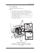
3. Remove the two (2) 1/4" hex screws securing the motor to the engine side
casting.
4. Loosen the two (2) 1/16" allen screws securing the gear to the motor shaft.
Refer to Figure 4-44.
5. Remove the gear from the motor shaft. Refer to Figure 4-44.
6. Using a 3/16" nut driver, remove the three hex screws securing the motor
bracket to the motor. Refer to Figure 4-44.
Replace:
1. Reverse the removal procedure to re-install either the supply cassette
motor A or B.
2. After installing the gear onto the supply motor, install the cassette and align
the motor gear to the cassette gear before tightening the two supply motor
gear allen screws.
3. Turn the system on and launch the AVDIAG program from the PC.
4. Test whichever (A or B) motor that was replaced.
4.7.3 Supply Spindle Select Motor
Tools Required: Screwdriver, allen wrench, phillips screwdriver
Remove:
1. Follow the first eight steps in Section 4.7.1, Supply Drive Servo Motor
above.
2. Remove the supply spindle select motor cable from the supply SDM board
at connector (J).
3. Remove the red wire from Pin 1 and the black wire from Pin 2 at the end
of the motor.
4. Remove the three (3) screws securing the inner light shield (shell surround-
ing the supply motors and sensors) to the imagesetter frame. Refer to
Figure 4-45. Pull the inner light shield out enough to expose the coupler
housing.
The coupler housing will have two access holes, one for each set of allen
screws. Refer to Figure 4-46. These allen screws secure the motor shaft to
the coupler.
5. Loosen one set of allen screws securing the motor shaft to the coupler.
Refer to Figure 4-46.
6. Remove the two (2) hex screws securing the motor bracket to the housing.
Refer to Figure 4-46.