
Service manual


Avantra 36/44 Service Manual
4-66 Removal and Replacement
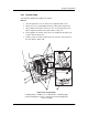
4.7.5 Supply Roller Removal and Installation
To Remove the Supply Rollers:
1. Move the nip supply drive roller to the spindle “A” roller.
2. If the system has a bridge, put the bridge in light mode and lift it up. You
do not have to disconnect the system from the buffer.
3. Turn the system off.
4. Remove the back supply cassette light shield.
5. Open top supply cassette cover.
To Remove the Bottom Roller:
1. Remove the three screws on each of the left and right inside gray light
shields covering the inside castings. The screws to remove these shields are
on the opposite side of each casting.
2. Remove the two screws securing the bottom left spring assembly on the
left inside casting, which holds the spindle “B” supply cassette bearing in
place.
3. Remove the two screws which secure the left and right black brackets,
holding the bottom roller bearings in place in the left and right inside cast-
ing. The two screws to remove these brackets are located on the opposite
sides of the left and right casting.
4. Remove the left and right/bottom and top supply cassette guides. The top
left and right guides are secured by two phillips screws on the inside cast-
ing and the bottom left and right guides are secured by two allen screws
on the inside casting. These four pieces are pinned so that they will not
require re-alignment when they are re-installed.
NOTE: Only remove all four supply cassette guides if all three roll-
ers are being replaced.
5. Pull the bottom roller from the left side first and then remove from the sys-
tem.
To Remove the Top Roller:
1. Remove the two screws securing the left side of bow tie plastic piece that
wraps around the shuttle motor rod. Do not remove the bar or loosen the
right side (the motor side). Remove the big shoulder screw located below
that piece and remove both pieces. The two screws and shoulder screw are
located on the outside left casting.
2. Remove the two screws securing each of the left and right black brackets
holding the top roller bearings in place in the inside casting. The two
screws to remove these brackets are located on the opposite sides of the
left and right casting.