
Service manual


Section III: Buffer
Installation 1-17
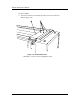
21. Press the gasket membrane provided (see Figure 1-5) onto the buffer at the
harness hole. Refer to Figure 1-15.
The harness hole is located on the right hand side of the buffer at the front
and near the bottom.
Figure 1-15 Routing the buffer harness cable through hole
(right, bottom, inside front).
➀–Wire bundle.
22. Route the wire bundle through the rubber gasket and into the imagesetter.
Refer to Figure 1-15.
1