
Service manual


Section IV: On-line Processor
Installation 1-21
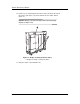
5. Remove the upper entry platen from the entrance rack. Refer to Figure 1-16.
6. Roll the imagesetter with the buffer attached to the OLP. The buffer and OLP
must interface as shown in Figure 1-16.
Figure 1-16 The buffer and OLP interface.
➀–Buffer interface. ➁– OLP front plate. ➂–Lower platen of entry rack.
➃–Upper platen (removed during the interface alignment).
1
2
4
3