
Service manual


Section IV: On-line Processor
Maintenance 4-11
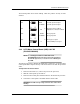
The following table shows switch settings. Check the position accuracy of these
switches.
u
= normal; i.e., factory setting
4.3.2 LUTH Motor Control Board (LMB) 180V DC
(P/N 5203Y4000200)
NOTE: The following procedure is for OLPs with serial
#3613DD300658 and below. Unless previously upgraded to
the 24 V DC style motor, see Sectin 4.3.1 for calibrating the
24 V LMB.
The following procedure calibrates the LMB (refer to Figure 4-3). A shorter remote
control panel cable is taped to the top of the electronics box to make the procedure
easier.
To Reposition the Control Panel:
1. Disconnect the mains (i.e., remove all power to the processor).
2. Slide the control panel up and remove.
3. Disconnect the control panel cable and take it to the back of the processor.
4. Connect the control panel to the X400 with the remote cable.
WARNING: The PCB has high voltage terminals. Use caution when
handling.
X201
S201
S202
S203
OPEN
u CLOSED
A
u AB
OPEN
u CLOSED
A
u B
4-circuit optical interrupter
3-circuit optical interrupter
Armature voltage feedback
Digital tacho + armature feedback
Analog input 5V
Analog input 10V
Analog preset signal
Infrared PWM preset signal
AB
AB