Agilent Technologies 11713A Attenuator/Switch Driver Operating and Service Manual Part Number: 11713-90023 Printed in USA Print Date: July 2001 Supersedes: August 1999 .
Notice The information contained in this document is subject to change without notice. Agilent Technologies makes no warranty of any kind with regard to this material, including, but not limited to, the implied warranties of merchantability and fitness for a particular purpose. Agilent Technologies shall not be liable for errors contained herein or for incidental or consequential damages in connection with the furnishing, performance, or use of this material.
Warranty Certification Agilent Technologies certifies that this product met its published specifications at the time of shipment from the factory. Agilent Technologies further certifies that its calibration measurements are traceable to the United States National Institute of Standards and Technology (NIST, formerly NBS), to the extent allowed by the Institute’s calibration facility, and to the calibration facilities of other International Standards Organization members.
PARTICULAR PURPOSE. EXCLUSIVE REMEDIES. THE REMEDIES PROVIDED HEREIN ARE BUYER’S SOLE AND EXCLUSIVE REMEDIES. AGILENT TECHNOLOGIES SHALL NOT BE LIABLE FOR ANY DIRECT, INDIRECT, SPECIAL, INCIDENTAL, OR CONSEQUENTIAL DAMAGES, WHETHER BASED ON CONTRACT, TORT, OR ANY OTHER LEGAL THEORY. Assistance Product maintenance agreements and other customer assistance agreements are available for Agilent Technologies products.
Contacting Agilent Any adjustment, maintenance, or repair of this product must be performed by qualified personnel. Contact your customer engineer through your local Agilent Techhnologies Service Center. If you do not have access to the Internet, one of these Agilent Technologies centers can direct you to your nearest representative: Online assistance: www.agilent.
Safety and Regulatory Information Review this product and related documentation to familiarize yourself with safety markings and instructions before you operate the instrument. This product has been designed and tested in accordance with international standards. WARNING The WARNING notice denotes a hazard. It calls attention to a procedure, practice, or the like, that, if not correctly performed or adhered to, could result in personal injury.
This symbol indicates that the power line switch is OFF Safety Earth Ground This is a Safety Class I product (provided with a protective earthing terminal). An uninterruptible safety earth ground must be provided from the main power source to the product input wiring terminals, power cord, or supplied power cord set. Whenever it is likely that the protection has been impaired, the product must be made inoperative and secured against any unintended operation.
General Safety Considerations WARNING • This product has been designed and tested in accordance with IEC Publication 1010, Safety Requirements for Electronic Measuring Apparatus, and has been supplied In a safe condition. The Instruction documentation contains information and warnings which must be followed by the user to ensure safe operation and to maintain the product In a safe condition. • The ON//OFF switch or the detachable power cord is the instrument disconnecting device.
• 11713A Operating and Service Manual ix
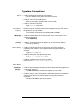
Typeface Conventions Italics • Used to emphasize important information: Use this software only with the xxxxxX system. • Used for the title of a publication: Refer to the xxxxX, System-Level User’s Guide • Used to indicate a variable: Type LOAD BIN filename. Instrument • Used to show on-screen prompts and messages that you will see on Display the display of an instrument: The xxxxxX will display the message CAL1 SAVED.
Contents 1. Agilent Technologies 11713A Attenuator/Switch Driver Overview . . . . . . . . . . . . . . . . . . . . . . . . . . . . . . . . . . . . . . . . . . . . . . . . . . . . . . . . . . . . . . . . . . .1-2 Compatible Attenuators and Switches . . . . . . . . . . . . . . . . . . . . . . . . . . . . . . . . . . . . . . . . .1-3 2. Installing the Agilent Technologies 11713A Attenuator/Switch Driver Initial Inspection . . . . . . . . . . . . . . . . . . . . . . . . . . . . . . . . . . . . . . . . . . . . .
Contents 6. Remote Operation GPIB Compatibility . . . . . . . . . . . . . . . . . . . . . . . . . . . . . . . . . . . . . . . . . . . . . . . . . . . . . . . . . . 6-2 Remote Mode . . . . . . . . . . . . . . . . . . . . . . . . . . . . . . . . . . . . . . . . . . . . . . . . . . . . . . . . . . . . . 6-2 Local Mode . . . . . . . . . . . . . . . . . . . . . . . . . . . . . . . . . . . . . . . . . . . . . . . . . . . . . . . . . . . . . . . 6-2 Addressing . . . . . . . . . . . . . . . . . . . . . . . . . . .
Contents Isolating a Malfunction. . . . . . . . . . . . . . . . . . . . . . . . . . . . . . . . . . . . . . . . . . . . . . . . . . . . . .8-5 Parts Identification . . . . . . . . . . . . . . . . . . . . . . . . . . . . . . . . . . . . . . . . . . . . . . . . . . . . . . . . .8-7 Figure 8-2 11713A Attenuator/Switch Driver Top Cover Removed . . . . . . . . . . . . . . . . . . .8-8 Figure 8-3 11713A Attenuator Switch Driver Bottom Cover Removed . . . . . . . . . . . . . . . .
1 Agilent Technologies 11713A Attenuator/Switch Driver Overview In this chapter you will find: • Function, features, and capabilities of the 11713A attenuator/switch driver • Compatible Agilent Technologies switches and attenuators
Agilent Technologies 11713A Attenuator/Switch Driver Overview Overview The 11713A attenuator/switch driver is an GPIB compatible instrument designed to provide control of up to two four-section programmable step attenuators and two microwave coaxial switches. Features • Instrument control is accomplished manually from front panel pushbuttons or automatically over the GPIB interface bus. • Programing via the GPIB can be accomplished in simple one line statements.
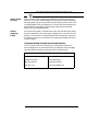
Agilent Technologies 11713A Attenuator/Switch Driver Overview Compatible Attenuators and Switches The 11713A attenuator/switch driver is designed to drive the following Agilent Technologies attenuators and switches. If you are using attenuators and switches made by another company, check their switching characteristics against those specified in Chapter 3, "Specifications".
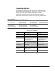
Agilent Technologies 11713A Attenuator/Switch Driver Overview Connecting Accessories Table 1-3 lists accessories that are available for the 11713A attenuator/switch driver. Supplied accessories include two dual Viking connector cables, 12-pin conductor, 60 inches long, and a line power cable. Refer to "Replaceable Parts".
2 Installing the Agilent Technologies 11713A Attenuator/Switch Driver Overview In this chapter you will learn about: • How to unpack and check your instrument • How to contact Agilent Technologies for service • Operating requirements for the attenuator/switch driver • How to set the GPIB address of your instrument • How to connect to switches, attenuators, and relays
Installing the Agilent Technologies 11713A Attenuator/Switch Driver Initial Inspection 1. Unpack and inspect the shipping container and its contents thoroughly to ensure that nothing was damaged during shipment. If the shipping container or cushioning material is damaged, the contents should be checked both mechanically and electrically. 2. If the contents are damaged or defective, contact your nearest Agilent Technologies Service and Support Office.
Installing the Agilent Technologies 11713A Attenuator/Switch Driver Verifying Requirements 7. Verify that you meet the following requirements. ❏ Power source ❍ 100 to 120 volts (+5%, –10%) from 48 to 440 Hz ❍ 220 to 240 volts (+5%, –10%) from 48 to 66 Hz, single phase. ❏ Power consumption ❍ 80 VA max CAUTION Before the instrument is switched on, it must be set to the voltage of the power source or damage to the instrument may result. Refer to Figure 2-1.
Installing the Agilent Technologies 11713A Attenuator/Switch Driver Figure 2-1 Line Voltage Selection WARNING To avoid the possibility of hazardous electrical shock, do not operate this Instrument at line voltages greater than 126.5 Vac with line frequencies greater than 66 Hz (leakage currents at these line settings may exceed 3.5 mA). ❏ Line Voltage and Fuse Selection a. Open the cover door of the line power module. Push the fuse-pull lever to the left and remove the fuse. (Refer to Figure 2-1.) b.
Installing the Agilent Technologies 11713A Attenuator/Switch Driver GPIB Addressing 8. Use the five-bit address switches located on the rear panel of the instrument to change the GPIB address. ❍ The 11713A has a factory preset address of decimal 28. The switch labeled with a one is the least significant bit. ❍ There are 32 possible addresses. Addresses 0 and 31 are typically reserved for GPIB functions and should not be used. IEE-488.1 limits the number of addressable elements (instruments) to 16.
Installing the Agilent Technologies 11713A Attenuator/Switch Driver Mating Connectors ❏ Mating connectors used with the driver are the 24-pin GPIB male, the 12-pin Viking Industries connector, and the banana type male. Figure 2-3 provides interconnection data for the General Purpose Interface Bus. Figure 2-3 General Purpose Interface Bus Connection Logic levels The interface bus logic levels are TTL compatible, that is, the true (1) state is 0.0 to +0.4 Vdc and the false (0) state is +2.5 to +5.0 Vdc.
Installing the Agilent Technologies 11713A Attenuator/Switch Driver Connecting to Attenuators and Switches ❏ Use the two plug-in drive cables supplied with the driver to connect to Attenuators and the multi-pin plugs on the rear panel. These attenuator cables have 12-pin connectors that may not be usable on some equipment. In these instances, the cable may be modified by removing a connector. A 9-wire cable with only one connector is also available. (Refer to Table 1-3.
Installing the Agilent Technologies 11713A Attenuator/Switch Driver Table 2-2 Attenuator Cable Connector Pin Numbers and Wire Color Codes Front Panel Pushbuttons a ATTENUATOR X, Y, and SWITCHES Pushbutton Number SWITCHE S 9 9 0 0 ATTENUATORS X Y 1 5 2 6 3 7 4 8 Pushbutton LEDs Rear Panel connectors ATTEN X or Y, and Attenuator Cable Pin Numbers Attenuator Cable Wire Color Code Red (24 Vdc) White/Brown (Gnd) ON OFF ON OFF 1 2 Connect to S9 and S0 outputs ATTEN X 3(S9-A) ATTEN X 4(S9-B0 ATTEN Y 3
Installing the Agilent Technologies 11713A Attenuator/Switch Driver Driving Additional Coaxial Switches ❏ Make switch connections to S0 outputs, S9 outputs, or to rear panel ATTEN X output or ATTEN Y output. Figure 2-4 shows the rear panel connections to S0 outputs and the GPIB command necessary to change the position of Agilent 8762 or 8765 series coaxial switches.
Installing the Agilent Technologies 11713A Attenuator/Switch Driver Figure 2-5 shows the rear panel connections and the GPIB command necessary to change the position of Agilent 8761B SPDT RF switches. (For GPIB command usage, refer to "Data Message Input Format" on page 6-3.) Figure 2-5 Connections for Agilent 8761B SPDT Switches ❏ GPIB command "B9" connects port C and port 2 and turns the front panel LED for pushbutton 9 OFF.
Installing the Agilent Technologies 11713A Attenuator/Switch Driver Connecting to Four-Section ❏ To use one four-section attenuator assembly, connect an attenuator cable to either the ATTEN X output (A6J1) or ATTEN Y output (A6J2). Connect both outputs to have more than four attenuator segments.
Installing the Agilent Technologies 11713A Attenuator/Switch Driver Connecting to Relays ❏ To drive ten devices, connect attenuator cables at ATTEN X and Y and switch cables to S9 and S0. A total of 10 relays may be on at one time if the total current is less than 650 mA. However, since there are dual transistor and relay drivers, where one driver is on while the other is off, a total of 20 relays may be controlled. Figure 2-7 shows the connections for a simplified relay driving circuit.
3 Specifications Overview In this chapter you will find: • Specifications which describe warranted performance standards • Supplemental characteristics which are non-warranted parameters
Specifications Specifications Specifications describe warranted performance over the temperature range 0 to +55 °C after one hour of continuous operation, unless otherwise noted. Table 3-1 Specifications Drive Power Supply Voltage + 24 ± 2.0 Vdc Current 1.3 A maximum peak for 1 second 0.65 A maximum continuous current Contact pairs 1 through 8, 9, and 0, maximum current of 0.
4 Verification Overview In this chapter you will find: • Recommended test equipment • How to verify local operation • How to verify GPIB interface remote operation
Verification Recommended Test Equipment Recommended Test Equipment Recommended Test Table 4-1 lists the test equipment required for performance verification and Equipment troubleshooting. Equipment other than the recommended models can be used provided the minimum specifications are satisfied.
Verification Operator’s Check for Local Operation Operator’s Check for Local Operation This check tests initial driver turn-on and local operation. Check that the following initial conditions are met before you proceed. ❏ Verify that driver power transformer primary is matched to the line voltage by the Line Voltage Selection Card. ❏ Check the driver power fuse for correct rating. Current fuse ratings for various line voltages are given on the line power module on rear panel.
Verification Operator’s Check for Local Operation 2. Press the LINE ON/OFF switch to ON. Switch should remain in the ON position and the green switch indicator LED should illuminate. All numbered pushbutton LEDs should be on and LOCAL LED should be on. 3. Depress the 10 numbered pushbuttons on the driver front panel. Each LED should alternate between off and on as each key is pressed.
Verification GPIB Interface Check for Remote Operation GPIB Interface Check for Remote Operation These procedures check the driver’s ability to process the GPIB messages described in the GPIB Message Reference Table 4-1. The checks can be performed together or separately. The validity of these checks are based on the following assumptions: • The driver operates correctly with front panel control (that is, in local mode). This can be verified with the Local Operation check.
Verification GPIB Interface Check for Remote Operation The select code of the controller’s I/O is assumed to be 7. The address of the driver is assumed to be 28 (factory preset). This select code-address combination (728) is not necessary for these checks to be valid. If necessary, modify the program lines presented here with the appropriate combination for your instrument. Remote Message This check assumes that the driver is in the local state.
Verification GPIB Interface Check for Remote Operation Local Lockout and Clear Lockout/ Set Local Messages This check requires the bus to be in the remote state. Check that the driver’s REMOTE light is ON. Description Command Local Lockout: Send Local Lockout message. LOCAL LOCKOUT 7 Operator’s Response Press the LOCAL key on the driver front panel. The REMOTE LED should remain ON. If not, the driver failed to process the Local Lockout message.
5 Local Operation Overview In this chapter you will find: • Function and description of front panel controls, connectors, and indicators • Function and description of rear panel controls, connectors, and indicators
Local Operation Local Control Local Control Local control of the Agilent 11713A switch driver is accomplished manually from front panel pushbuttons. Figure 5-1 and Figure 5-2 detail front and rear panel controls, connectors, and indicators.
Local Operation Local Control Figure 5-l Front Panel Features [1] ATTENUATOR X [4] LOCAL In the local mode, pushbutton switches 1, 2, 3, and 4 activate solid state switches (current sinks) to change the attenuation setting of an attenuator connected to the ATTEN X connector on the rear panel. Pushbutton switch that resets to the local mode when not in local lockout. LED turns on in LOCAL mode.
Local Operation Local Control Figure 5-2 Rear Panel Features [1] ATTEN X [8] Fuse Connector to accept cable plug going to programmable attenuator X 1.
Remote Operation 6 Remote Operation Overview In this chapter you will learn about: • Remote programming capability of the attenuator/switch driver • Function and use of GPIB commands in remote mode • Programming information to set up desired level of attenuation 11713A Operating and Service Manual 6-1
Remote Operation The driver can be operated remotely through the General Purpose Interface Bus (GPIB). GPIB Compatibility Remote-only functions and all front panel functions (except the LINE switch) are programmable through the GPIB. The operator’s interface check in Chapter 4, "Verification" provides a test of the GPIB to verify that the driver can function with each of the applicable bus messages. Table 6-1 summarizes the driver’s GPIB capabilities in terms of the twelve bus messages.
Remote Operation Local Lockout The local lockout condition disables the front panel LOCAL key so that pressing the LOCAL key will not return the driver to local mode. When local lockout is in effect, the driver is returned to local under program control. (sending Clear Lockout/Set Local) or by turning the driver LINE switch OFF and ON. However, returning to local by switching to OFF and then ON, will defeat the purpose of local lockout and the system controller will lose control.
Remote Operation The data string is further defined as follows: Ax Bx Ay By A/B 9 A/B 0 where: Ax Bx = data string for ATTEN X (x can be none, one or more of the digits 1, 2, 3, or 4) Ay By = data string for ATTEN Y (x can be none, one or more of the digits 5, 6, 7, or 8) Note that if Ax (Ay) uses a digit, then that digit may not be used in Bx (By).
Remote Operation Receiving the Local Message The driver does not respond to the local message. When the driver is in Local Message remote mode, it can be returned to local mode with a Clear Lockout/Set Local message. The front panel LOCAL key can also return the driver to local mode. However, pressing the LOCAL key might interrupt a data message to the driver. This would leave the driver in a state unknown to the controller.
Remote Operation Table 6-1 summarizes the driver’s GPIB capabilities in terms of the twelve bus messages. Table 6-1 GPIB Message Reference Table GPIB Message Applicable Response Related Commands and Controlsa Interface Functions Data yes All front panel functions, except LINE ON/OFF switch, are programmable. The front panel REMOTE indicator turns on when addressed. Data No The driver does not respond to the trigger message GET DT0 Trigger No The driver does not respond to the clear message.
Remote Operation Table 6-2 gives the relationship between each programming code and the effect it has on the output at each connector/pin.
Remote Operation Table 6-3 shows the programming strings required to set up various three and four-section attenuators to the desired level of attenuation.
7 Replacing Major Assemblies Overview In this chapter you will find: • Replaceable parts and connecting accessories • Procedures for the removal and replacement of major assemblies in the 11713A attenuator/switch driver ❍ Module cover ❍ Front panel ❍ Rear panel ❍ A1 interconnect and power supply assembly ❍ A2 driver assembly ❍ A3 latch assembly ❍ A4 remote local logic assembly ❍ A5 GPIB handshake and data input assembly ❍ A6 interface assembly ❍ A7 switch board assembly ❍ A8 power mo
Replacing Major Assemblies Replaceable Parts Replaceable Parts Table 7-1 lists the accessories that are supplied with the 11713A attenuator/switch driver. Other available accessories are listed in Table 1-3. For ordering information, refer to "Service and Support" on page v in the front matter of this manual.
Replacing Major Assemblies Replaceable Parts Major assemblies and cables of the 11713A attenuator/switch driver are listed below.
Replacing Major Assemblies Replaceable Parts Table 7-5 Cabinet Parts Reference Designation Agilent Part Number Qty Description MP1 11713-00024 1 Front panel MP2 5021-8413 1 Front panel MP3 11713-00005 1 Sub panel MP4 5021-8413 1 Rear frame MP5 11713-00012 1 Rear panel MP6 5021-5829 2 Side strut MP7 5021-9253 1 Top cover, perforated MP8 5062-3871 1 Bottom cover, perforated MP9 5040-8801 2 Foot (standard) MP10 5040-8803 2 Foot, non-skid MP12 5001-0538 2 Side tri
Replacing Major Assemblies Module Cover Removal/Replacement Module Cover Removal/Replacement CAUTION This module contains components that can be damaged or destroyed by electrostatic discharge. It should be serviced at a static-safe workstation. Refer to "Preparing a Static-Safe Work Station" in Chapter 8. NOTE Top and bottom covers are removed and replaced similarly. To Remove Module Covers 1. Unscrew the one single screw in the middle of the cover flange that holds the cover to the rear panel. 2.
Replacing Major Assemblies Front Panel Removal/Replacement Front Panel Removal/Replacement CAUTION This module contains components that can be damaged or destroyed by electrostatic discharge. It should be serviced at a static-safe workstation. Refer to "Preparing a Static-Safe Work Station" in Chapter 8. To Remove the Front Panel 1. Remove the top and bottom covers. Refer to "Module Cover Removal/Replacement". 2. Remove the four corner screws that hold the front panel to the frame. 3.
Replacing Major Assemblies Rear Panel Removal/Replacement Rear Panel Removal/Replacement CAUTION This module contains components that can be damaged or destroyed by electrostatic discharge. It should be serviced at a static-safe workstation. Refer to "Preparing a Static-Safe Work Station" in Chapter 8. To Remove the Rear Panel 1. Remove the top and bottom covers. Refer to "Module Cover Removal/Replacement". 2. Remove the two screws at the GPIB connector. 3.
Replacing Major Assemblies A1 Interconnect and Power Supply Assembly Removal/Replacement A1 Interconnect and Power Supply Assembly Removal/Replacement CAUTION This module contains components that can be damaged or destroyed by electrostatic discharge. It should be serviced at a static-safe workstation. Refer to "Preparing a Static-Safe Work Station" in Chapter 8. To Remove the A1 Interconnect/Power Supply Assembly 1. Remove the top and bottom covers. Refer to "Module Cover Removal/Replacement". 2.
Replacing Major Assemblies A2 Driver Assembly Removal/Replacement A2 Driver Assembly Removal/Replacement CAUTION This module contains components that can be damaged or destroyed by electrostatic discharge. It should be serviced at a static-safe workstation. Refer to "Preparing a Static-Safe Work Station" in Chapter 8 To Remove the A2 Driver Assembly 1. Remove the top cover. 2. With a strong upward motion, lift the red ring at the top edge of the A2 driver and remove the assembly.
Replacing Major Assemblies A3 Latch Assembly Removal/Replacement A3 Latch Assembly Removal/Replacement CAUTION This module contains components that can be damaged or destroyed by electrostatic discharge. It should be serviced at a static-safe workstation. Refer to "Preparing a Static-Safe Work Station" in Chapter 8. To Remove the A3 Latch Assembly 1. Remove the top cover. 2. With a strong upward motion, lift the orange ring at the top edge of the A3 latch assembly. To Replace the A3 Latch Assembly 1.
Replacing Major Assemblies A4 Remote Local Logic Assembly Removal/Replacement A4 Remote Local Logic Assembly Removal/Replacement CAUTION This module contains components that can be damaged or destroyed by electrostatic discharge. It should be serviced at a static-safe workstation. Refer to "Preparing a Static-Safe Work Station" in Chapter 8. To Remove the A4 Remote Local Logic Assembly 1. Remove the top cover. 2.
Replacing Major Assemblies A5 GPIB Handshake Data Input Assembly Removal/Replacement A5 GPIB Handshake Data Input Assembly Removal/Replacement CAUTION This module contains components that can be damaged or destroyed by electrostatic discharge. It should be serviced at a static-safe workstation. Refer to "Preparing a Static-Safe Work Station" in Chapter 8. To Remove the A5 GPIB Assembly 1. Remove the top cover 2.
Replacing Major Assemblies A6 Interface Assembly Removal/Replacement A6 Interface Assembly Removal/Replacement CAUTION This module contains components that can be damaged or destroyed by electrostatic discharge. It should be serviced at a static-safe workstation. Refer to "Preparing a Static-Safe Work Station" in Chapter 8. To Remove the A6 Interface Assembly 1. Remove both covers. Unscrew one screw on each cover and then slide the cover toward the rear. 2.
Replacing Major Assemblies A7 Switch Board Assembly Removal/Replacement A7 Switch Board Assembly Removal/Replacement CAUTION This module contains components that can be damaged or destroyed by electrostatic discharge. It should be serviced at a static-safe workstation. Refer to "Preparing a Static-Safe Work Station" in Chapter 8. To Remove the A7 Switch Board Assembly 1. Remove both covers. Unscrew one screw on each cover and then slide the cover toward the rear. 2.
Replacing Major Assemblies A8 Power Supply/Line Filter Assembly Removal/Replacement A8 Power Supply/Line Filter Assembly Removal/Replacement CAUTION This module contains components that can be damaged or destroyed by electrostatic discharge. It should be serviced at a static-safe workstation. Refer to "Preparing a Static-Safe Work Station" in Chapter 8. To Remove the A8 Power Supply/Line Filter Assembly 1. Locate the line filter unit behind the power connector where power cable plugs in. 2.
8 Servicing the Attenuator/Switch Driver Overview In this chapter you will find: • How to prepare a static-safe work station • How to replace the rear-panel fuse • Troubleshooting hints for diagnosing common problems • Assembly level troubleshooting
Servicing the Attenuator/Switch Driver Preparing a Static-Safe Workstation Preparing a Static-Safe Workstation Electrostatic discharge (ESD) can damage or destroy electronic components. All work performed on assemblies consisting of electronic components should be done at a static-safe workstation.
Servicing the Attenuator/Switch Driver Preparing a Static-Safe Workstation • Before connecting any coaxial cable to an instrument connector for the first time each day, momentarily ground the center and outer conductor of the cable. • Handle all PC board assemblies and electronic components only at static-safe work stations. • Store or transport PC board assemblies and electronic components only in static-shielding containers.
Servicing the Attenuator/Switch Driver Maintenance and Adjustments Maintenance and Adjustments Fuse Removal/Replacement User maintenance is limited to replacement of the rear panel fuse. The main ac line fuse is located on the rear panel in the line power module. Use the following procedure to remove the fuse. Refer to Figure 3-2. 1. Remove the line power cable from its jack. 2. Open the cover door of the line power module. 3. Push the fuse-pull lever to the left and remove the fuse. 4.
Servicing the Attenuator/Switch Driver Troubleshooting Troubleshooting Isolating a Malfunction Use the following procedure to help you isolate a malfunction. ❏ Recommended test equipment for troubleshooting is listed in Table 4-1. ❏ Figure 8-2 and Figure 8-3 identify the assemblies and test points specified in the steps below. Procedure 1. Remove the switch driver top cover. Refer to "Module Cover Removal/Replacement". 2. Turn on the driver and verify that the proper power up status is reached.
Servicing the Attenuator/Switch Driver Troubleshooting c. Verify that the pulse reaches the clock input of A3 latch assembly driver assembly storage register flip-flops. Verify that the Q and NQ outputs change state as the corresponding pushbutton is exercised. d. Measure input and output levels of inverting drivers on the A2 driver assembly. e. If all logic levels up to the Darlington transistors operate, check for shorted or open Darlington transistors.
Servicing the Attenuator/Switch Driver Troubleshooting Parts Identification Figure 8-2 and Figure 8-3 identify the location of the following assemblies and parts referred to in troubleshooting procedures.
Servicing the Attenuator/Switch Driver Troubleshooting Figure 8-2 11713A Attenuator/Switch Driver Top Cover Removed 8-8 11713A Operating and Service Manual
Servicing the Attenuator/Switch Driver Troubleshooting Figure 8-3 11713A Attenuator Switch Driver Bottom Cover Removed 11713A Operating and Service Manual 8-9
A2 Driver P/O A6 Interface Attenuator X-Drivers A7 Front Panel ATTEN X Local Attenuator X and Y Switches DS1-DS0 LEDS +24 V +5 V +24 V Common S1-S0 1-0 A4 Remote Local Logic A3 Latch 1-8 Driver Storage Registers SW1 through SW0 OneShots » 17ms Remote/Local 2 to 1 Multiplexer ATTEN Y CLK CLK 1 through CLK 0 Power Up LOCAL Attenuator Y-Drivers FF S9 1 through 0 Remote/Local Light A J&K Inputs +5 V Switch 9 and 0 Drivers REMOTE B +5 V +5 V S0 9,0 A A 2 P/O A6 Interface B Addr
Servicing the Attenuator/Switch Driver Troubleshooting the A1 Interconnect Assembly Troubleshooting the A1 Interconnect Assembly The A1 interconnect assembly contains the power supply and connectors for other major assemblies. To Troubleshoot the A1 Interconnect Assembly 1. Pull out the A2 driver, A3 latch, A4 remote local logic, and A5 GPIB board assemblies. 2. Turn the power on, and measure the voltage at TP1 on the A1 interconnect assembly. 5 Vdc ± 5% should be present. 3. Measure the voltage at TP2.
Servicing the Attenuator/Switch Driver Troubleshooting the A2 Driver Assembly Troubleshooting the A2 Driver Assembly The A2 driver assembly is controlled by inputs from the A3 latch assembly which is clocked by either the A7 front panel switches or from the GPIB through the A4 remote local logic assembly. To Troubleshoot the A2 Driver Assembly 1. To determine the problem board assembly, test them in the following sequence: A1 interconnect, A7 switch, A5 GPIB, A4 remote local logic, A3 latch, and A2 driver.
Servicing the Attenuator/Switch Driver Troubleshooting the A2 Driver Assembly Assembly Overview The A2 driver assembly contains eight pairs of driver transistors and two driver relays. One transistor of each pair, for example, Q9 and Q18, is in saturation while the other transistor is in cutoff. The saturated transistor sinks current from the + 24 Vdc supply through the load connected to the rear panel of the driver and returns it to ground.
Servicing the Attenuator/Switch Driver Troubleshooting the A3 Latch Assembly Troubleshooting the A3 Latch Assembly The A3 latch assembly contains 10 J-K flip-flops and a power-up circuit. To Troubleshoot the A3 Latch Assembly 1. If any of the following conditions cannot be met, replace the A3 latch assembly. a. Turn the power off and then turn it on again. All attenuator lights and the local light should be on. b. Press each attenuator switch. Only the corresponding light should turn off.
Servicing the Attenuator/Switch Driver Troubleshooting the A4 Local Logic Assembly Troubleshooting the A4 Local Logic Assembly The A4 local logic assembly contains a remote/local flip-flop, an A or B flip-flop, a four-line to ten-line decoder, a local lockout flip-flop, listen flip-flop, 10 two-line to one-line multiplexers, and the required circuitry to generate a clock signal to control the operation of the four- to ten-line decoder. To Troubleshoot the A4 Local Logic Assembly 1.
Servicing the Attenuator/Switch Driver Troubleshooting the A5 Handshake and Data Input Assembly Troubleshooting the A5 Handshake and Data Input Assembly The A5 handshake and data input assembly provides the interface between the bus and the driver. To Troubleshoot the A5 Handshake and Data Input Assembly 1.
Servicing the Attenuator/Switch Driver Troubleshooting the A5 Handshake and Data Input Assembly The bus logic performs the following functions: • accepts inputs from the data input/output (DIO) lines and the attention (ATN) signal from the interface bus. These inputs, in conjunction with the HS OUT signal, enable the remote/local logic and the local lockout logic. • processes the attenuator/switch state codes and select codes present on the DIO lines.
Servicing the Attenuator/Switch Driver Troubleshooting the A6 Interface Assembly Troubleshooting the A6 Interface Assembly The A6 interface assembly contains the GPIB address switch, the connectors for the X and Y attenuators, and the wiring for switch outputs 9 and 0. To Troubleshoot the A6 Interface Assembly 1. To test the circuitry of the A6 interface assembly, check the driver both in manual and remote operation. a. Manually press the attenuator buttons several times.
Servicing the Attenuator/Switch Driver Troubleshooting the A7 Switch Board Assembly Troubleshooting the A7 Switch Board Assembly The A7 switch board assembly (front panel) consists of 10 non-retriggerable monostable multivibrators. To Troubleshoot the A7 Switch Board Assembly 1. Check both manual and remote operation. a. To check the driver in manual operation, turn the driver off and then on. All attenuator lights and the local light should be on. b.
Servicing the Attenuator/Switch Driver Troubleshooting the A7 Switch Board Assembly LOCAL and REMOTE LEDs signify the operating mode of the driver. A reset circuit clears the LOCAL-REMOTE flip-flop on the A4 remote local assembly to the local state unless the instrument is in local lockout. The ON/OFF LED is operated from the +5 Vdc supply. In remote operation, a bus command sets the listen flip-flop to accept further bus commands. The listen flip-flop resets when a local command is given.
Servicing the Attenuator/Switch Driver The A8 power supply/line module assembly The A8 power supply/line module assembly The A8 power supply/line assembly houses the power receptacle, fuse, and voltage selector PC board. To Troubleshoot the A8 Power Supply/Line Module Assembly 1. If the attenuator/switch driver does not power on when the line button is pressed ON, check that the fuse is good. The main ac line fuse is located on the rear panel in the line power module. Refer to "Fuse Removal/Replacement".
Index A address codes 2-5 address switches 2-5 adjustments 8-4 assemblies 7-3 attenuation levels 6-8 attenuator/switch driver local operation 5-1 malfunction 8-5 remote operation 6-1 trouble shooting 8-5 wire color codes 2-8 B bench operation 2-2 C cables internal 7-3 restrictions 2-6 characteristics, supplemental 3-2 clear lockout message 4-7 coaxial switches 2-9 compatible switches/ attenuators 1-3 connecting to attenuator drivers 2-7 connectors mating 2-6 pin numbers 2-8 continuous current 2-12 D data me
clear 6-4 clear lockout 6-5 data 4-6 local 6-5 lockout 6-5 pass control 6-5 set local 6-5 trigger 6-4 remote mode 6-2 remote operation check 4-5 remote-to-local 6-2 replacing major assemblies 7-1 returning your instrument 2-2 S sending messages data 6-4 require service 6-5 status bit 6-5 status byte 6-5 servicing your instrument 2-2 set local message 4-7 supplemental characteristics 3-2 T test equipment 8-5 Troubleshooting 8-5 V verification local operation 4-3 remote operation 4-5 Index 2 11713A Operating