
Service manual


6-6 11713A Operating and Service Manual
Remote Operation
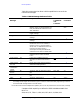
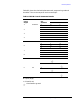
Table 6-1 summarizes the driver’s GPIB capabilities in terms of the
twelve bus messages.
Table 6-1 GPIB Message Reference Table
Complete GPIB capability as defined in IEEE Std 488 and ANSI Std
MC1.1 is:
SH0, AH1, T0, TE0, L2, LE0, DC0, DT0, RL1, C0, SR0, PP0.
GPIB
Message
Applicable Response Related
Commands
and
Controls
a
Interface
Functions
Data yes All front panel functions, except LINE
ON/OFF switch, are programmable. The
front panel REMOTE indicator turns on
when addressed.
TO, L2, AH1,
SH0
Data No The driver does not respond to the
trigger message
GET DT0
Trigger No The driver does not respond to the clear
message.
DCL, SDC DC0
Clear No The driver does not respond to the clear
message
REN
RL1
b
Remote Yes The driver remote mode is enabled when
the REN bus line is true. However, R
remains in local (i.e, the front panel is
active) until it is addressed to listen the
first time. The output signal is
unchanged. The front panel REMOTE
indicator turns on when in remote mode.
GTL
RL1
b
Local No The driver does not respond to the Local
message. Refer to Clear Lockout/set
Local.
LLO
RL1
b
Local Lockout Yes LOCAL key is disabled. Only the
controller can return to the driver to
local.
REN
RL1
b
Clear Lockout/
Set Local
Yes Driver goes to local and local lockout is
cleared when REN goes false.
RL1
b
Pass
Control/Take
Control
No The driver has no controller capability SRQ SR0
Require
Service
No The driver does not respond to a serial
poll.
SPE, SPD T0
Status Byte No The driver does not respond to a parallel
poll.
PP0
Abort No The driver stops listening IFC T0,L2
a.Commands, control lines and Interface functions are defined in IEEE Std 488 and ANSI Sid MC1.1.
Knowledge of these might not be necessary if your controller’s manual describes programming in terms of
the twelve GPIB messages shown in the left column.
b.The driver does not have complete RU capability since it can not process the Go-To-Local (GTL) message.