
Technical data

Chapter 6 113
Channel Analyzer Measurements
Making Adjacent Channel Power (ACP) Measurements
Channel Analyzer Measurements
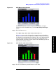
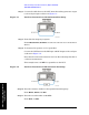
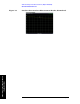
Figure 6-2 ACP Measurement Results
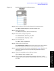
The frequency offsets, channel integration bandwidths, and span
settings can all be modified when you select
Meas Setup, Format Type
(Cust).
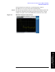
Step 7. Turn the limit test on:
Press
Meas Setup, Limits, Power Limits, Power Limits (On).
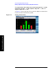
In Figure 6-4 notice that all offsets have passed except ACP 2 High.
Power levels that exceed our specified
−65 dBm for offsets ACP 2 High,
fail. Failures are identified by the red letter “F” on the displayed levels
of the bar graph and the red color of the dBc value displayed in the
results window at the bottom of the screen. The offset bar graph is also
shaded red to identify a failure.
Figure 6-3 ACP Results with Offset Limits
Step 8. You may set different pass/fail limits for each offset: