
Technical data

118 Chapter 7
Stimulus Response Measurements (Option N8995A)
Two Port Insertion Loss
Stimulus Response Measurements
(Option N8995A)
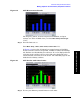
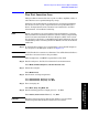
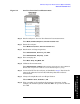
Step 7. Connect the cable (but not the DUT) from the tracking generator output
to the analyzer input as shown in Figure 7-1.
Figure 7-1 Two Port Insertion Loss Normalization Test Setup
Step 8. Normalize the frequency response:
Press
FREQ Channel, Normalize and follow the instructions on the Normalize
Wizard.
Step 9.
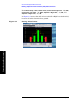
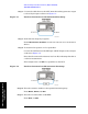
To measure the rejection of a low pass filter:
Connect the DUT between the RF Input and RF Output of the analyzer
as shown in Figure 7-2.
Note that the units of the reference level are dB, indicating that this is
a relative measurement.
This example uses a 50 MHz low pass filter as the DUT.
Figure 7-2 Two Port Insertion Loss Measurement Test Setup
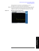
Step 10. Place the reference marker at the specified cutoff frequency:
Press
Marker, Normal, 50, MHz.
Step 11. Place the second marker at 100 MHz:
Press
Delta, 50, MHz.