
Technical data

120 Chapter 7
Stimulus Response Measurements (Option N8995A)
One Port Insertion Loss
Stimulus Response Measurements
(Option N8995A)
One Port Insertion Loss
The one port insertion loss measurement allows you to quantify signal
loss in a cable or other device without connecting both ends to the
analyzer. This measurement can be especially useful in measuring the
loss of a feedline connected to the antenna on a tower.
This measurement is less accurate than two port insertion loss,
however. Therefore, when it’s practical to connect both ends of a device
to the analyzer—for example, for short cables or attenuators—it is
better to use two port insertion loss.
NOTE Test signals can cause interference. When testing cables attached to
antennas, test signals are radiated. Verify that the signal used for the
test cannot cause interference to another antenna.
NOTE The One Port Insertion Loss calibration is the same calibration as
performed for two other measurements: Return Loss and Distance to
Fault (as long as you use the manual frequency method). If you make
the calibration for any of these three measurements, the calibration will
apply to the other two measurements and “Calibrated” will be displayed
on the screen for all three.
The calibration remains valid until you power off the analyzer or
change the start or stop frequency.
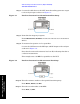
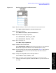
Step 1. Connect the calibrating devices to the analyzer RF Input when
prompted in the procedure, as shown in Figure 7-4, or in the calibration
wizard.
NOTE DO NOT make the connection at this time. You will be directed when to
make the connections later in the procedure.
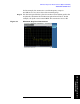
This example uses a 15 foot cable as the DUT.