
Technical data

Chapter 7 121
Stimulus Response Measurements (Option N8995A)
One Port Insertion Loss
Stimulus Response Measurements
(Option N8995A)
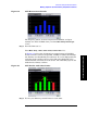
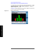
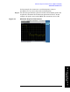
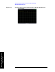
Figure 7-4 One Port Insertion Loss Measurement
Step 2. Set the analyzer to the One Port Insertion Loss measurement:
Press
Mode, Stimulus/Response, One Port Insertion Loss
Step 3.
Preset the analyzer:
Press
Mode Preset, Meas, One Port Insertion Loss.
Step 4. Set the start and stop frequencies:
Press
FREQ Channel, Start Freq, 100, MHz.
Press
FREQ Channel, Stop Freq, 2, GHz.
Step 5. Turn averaging off:
Press
Meas Setup, Avg Mode, Off.
Step 6. Calibrate the measurement:
Press
FREQ Channel, Calibrate and follow the instructions on the Calibration
Wizard. The analyzer will calibrate over the desired frequency range.
Step 7.
Connect the DUT to the analyzer, as described in step 1. Note that the
units of the reference level are dB, indicating that this is relative
measurement.
Step 8. Change the amplitude scale to 2 dB per division:
PRess
AMPTD Y Scale, Scale/Div, 2, dB.
Step 9. Place a marker on the results at the frequency of interest. In this
example, the marker is placed at 986.667 MHz. As you can see the loss
is 2.1 dB.