
Technical data


Chapter 7 123
Stimulus Response Measurements (Option N8995A)
Return Loss
Stimulus Response Measurements
(Option N8995A)
Return Loss
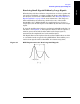
Return loss is a measure of reflection characteristics. One way you can
use the return loss measurement is to detect problems in an antenna
feedline system or the antenna itself. A portion of the incident power
will be reflected back to the source from each transmission line fault as
well as the antenna. The ratio of the reflected voltages to the incident
voltage is called the reflection coefficient. The reflection coefficient is a
complex number, meaning it has both magnitude and phase
information. In S-parameter terms, Return Loss is referred to as an S
11
measurement.
NOTE Test signals can cause interference. When testing cables attached to
antennas, test signals are radiated. Verify that the signal used for the
test cannot cause interference to another antenna.
NOTE The Return Loss calibration is the same calibration as performed for
One Port Insertion Loss and Distance to Fault (as long as you use the
manual frequency method). If you make the calibration for any of these
three measurements, the calibration will apply to the other two
measurements and “Calibrated” will be displayed on the screen for all
three.
The calibration remains valid until you power off the analyzer or
change the start or stop frequency.
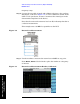
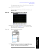
Step 1. Set the analyzer to the Stimulus/ Response Mode and the Return Loss
measurement:
Press
Mode, Stimulus/Response, Return Loss
Step 2.
Preset the analyzer:
Press
Mode Preset, Meas, Return Loss.
Step 3. Set the start and stop frequencies:
Press
FREQ Channel, Start Freq, 10, MHz.
Press
FREQ Channel, Stop Freq, 250, MHz.
Step 4. Turn averaging off:
Press
Meas Setup, Averaging, Off.
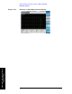
Step 5. Calibrate the measurement:
Press
FREQ Channel, Calibrate and follow the instructions on the
Calibration Wizard. The analyzer will calibrate over the desired