
Technical data


134 Chapter 8
Concepts
Stimulus Response Measurement Concepts
Concepts
Stimulus Response Measurement Concepts
NOTE Stimulus response measurements require the N8995A Stimulus
Response Measurement Suite and either option TG3 or TG6.
Stimulus Response Overview
Stimulus response measurements require a source to stimulate a device
under test (DUT), a receiver to analyze the frequency response
characteristics of the DUT, and, for return loss measurements, a
directional coupler or bridge. The Agilent CSA tracking generator
options include a built-in RF bridge. Characterization of a DUT can be
made in terms of its transmission or reflection parameters. Examples of
transmission measurements include flatness and rejection. Return loss
is an example of a reflection measurement.
A spectrum analyzer combined with a tracking generator forms a
stimulus response measurement system. With the tracking generator
as the swept source and the analyzer as the receiver, operation is the
same as a single channel scalar network analyzer. The tracking
generator output frequency must be made to precisely track the
analyzer input frequency for good narrow band operation. A narrow
band system has a wide dynamic measurement range. This wide
dynamic range will be illustrated in the following example.
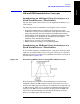
There are three basic steps in performing a stimulus response
measurement, whether it is a transmission or a reflection
measurement. The first step is to set up the analyzer, the second is to
normalize, and the last step is to perform the measurement.
Normalization Concepts
To make a transmission measurement accurately, the frequency
response of the test system must be known. Normalization is used to
eliminate this error from the measurement. To measure the frequency
response of the test system, connect the cable (but not the DUT) from
the tracking generator output to the analyzer input.
Press
Mode, Stimulus/Response, Two Port Insertion Loss. Set the desired
start and stop frequencies. Press
Normalize, Continue.
The frequency response of the test system is automatically stored and a
normalization is performed. This means that the active displayed trace
is now the ratio of the input data to the data stored in memory.
When normalization is on, trace math is performed on the active trace,
with the result placed into the selected trace.
Reconnect the DUT to the analyzer. Note that the units of the reference