
Technical data


Chapter 3 59
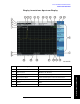
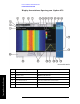
Front and Rear Panel Features
Front Panel Overview
Front and Rear Panel Features
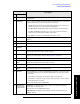
7 Over Range: Indicates that the
attenuation and preamp (if installed)
settings are supplying too much
power to the detector. Distortion may
result. Set
Auto Range (On) to clear.
or
<8 Smpl/Pt: Indicates that the
current instrument settings have
reduced the number of
samples/display point to less than 8.
The most accurate averaged
amplitude measurement will be made
when you have at least 8 samples in
each display point.
AMPTD Y Scale, Elec Atten
AMPTD Y Scale, Internal Preamp
AMPTD Y Scale, Auto Range
Trace/Detector
, Detector, Average (Log/RMS/V)
8Ext Gain
AMPTD Y Scale, Ext Gain
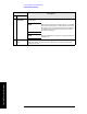
9 Color scale legend Provides a reference for the color scale.
10 Elapsed time clock Provides an indicator of the data collection time interval
of the displayed spectrogram.
11 Time and date display
System, Time/Date/Location, Date/Time
12 Active marker Marker
13 Trace information Trace/Detector, Clear Write (W) Average (A) Max Hold (M) Min
Hold (m)
Trace/Detector
, Peak (P) Sample (S) Negative Peak (p)
Average (A)
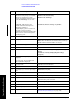
14 Active marker frequency and
amplitude
Marker
15 Key menu title Dependent on menu selection.
16 Key menu Menu key labels
17 Stop frequency or if in zero span, stop
time
FREQ Channel, Stop Freq
18 Reference frequency source indicator
System, Freq/Time Reference
19 Battery 1 & 2 status indicator System, System Stats, Battery
20 AC power indicator Indicates that the analyzer is currently powered by the
external AC/DC power converter
21 Spectrum display
View/Display, Spectrogram Provides a Spectral display of
the spectrum sampled to create the spectrogram.
22 Start frequency or if in zero span,
0sec
FREQ Channel, Start Freq
23 Marker
Marker
24 Display status line Displays informational and error messages (see “Types of
Spectrum Analyzer Messages” on page 189).
Item Description Associated Function Keys