
Technical data

Chapter 5 89
Spectrum Analyzer
Measuring a Low−Level Signal
Spectrum Analyzer
Reducing Input Attenuation
The ability to measure a low-level signal is limited by internally
generated noise in the spectrum analyzer. The measurement setup can
be changed in several ways to improve the analyzer sensitivity.
The input attenuator affects the level of a signal passing through the
instrument. If a signal is very close to the noise floor, reducing input
attenuation can bring the signal out of the noise.
CAUTION Ensure that the total power of all input signals at the analyzer RF
input does not exceed +33 dBm (2 watts).
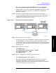
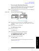
Step 1. Connect the RF Output of the signal generator to the analyzer RF Input
as shown in Figure 5-7.
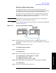
Figure 5-13 Setup for Obtaining One Signal
Step 2. Set the frequency of the signal source to 295 MHz. Set the source
amplitude to −80 dBm. Connect the source RF OUTPUT to the analyzer
RF INPUT.
Step 3. Select the spectrum analyzer mode:
Press
Mode, Spectrum Analyzer.
Step 4. Preset the analyzer:
Press
Mode Preset.
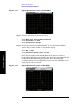
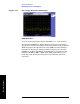
Step 5. Set the center frequency, span and reference level:
Press
FREQ Channel, Center Frequency, 295, MHz.
Press
SPAN X Scale, Span, 1, MHz.
Press
AMPTD Y Scale, Ref Level, 40, −dBm.
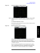
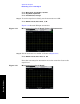
Step 6. Place the marker at the desired peak (in this example, 295 MHz)
Press
Peak Search.
Step 7. Activate averaging to smooth the noise: