
Technical data

96 Chapter 5
Spectrum Analyzer
Making Distortion Measurements
Spectrum Analyzer
Identifying Distortion Products
Distortion from the Analyzer
High level input signals may cause analyzer distortion products that
could mask the real distortion measured on the input signal. Using
trace 2 and the RF attenuator, you can determine which signals, if any,
are internally generated distortion products.
Identifying Analyzer Generated Distortion Example:
Using a signal from a signal generator, determine whether the
harmonic distortion products are generated by the analyzer.
Step 1. Connect a signal generator to the analyzer INPUT.
Step 2. Set the signal generator frequency to 200 MHz and the amplitude to
0dBm.
Step 3. On the analyzer, perform a mode preset by pressing Mode Preset.
Step 4. Set the center frequency of the analyzer to 400 MHz by pressing FREQ
Channel, Center Frequency, 400, MHz.
Step 5. Set the span to 500 MHz by pressing SPAN X Scale, Span, 500, MHz.
Step 6. Set the attenuation to 10 dB by pressing AMPTD Y Scale, Elec Atten,
10 dB.
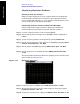
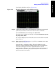
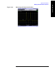
The signal produces harmonic distortion products in the analyzer input
mixer as shown in Figure 5-19.
Figure 5-19 Harmonic Distortion
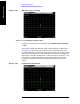
Step 7. Change the span to 50 MHz: press SPAN X Scale, Span, 50, MHz.
Step 8. Ensure that the signal is at the center frequency. If necessary press
Peak Search, Marker→, Mkr→CF.
Step 9. Change the attenuation to 0 dB: press AMPTD Y Scale, Elec Atten, 0, dB.